 [1]Leaf springs have been in cars for longer than most people can remember. And while they can serve their purpose in many classic cars on both the street and the track, there’s no denying that a dedicated link-style setup is going to be a much better performer. Leaf springs are old technology, and just about every modern vehicle on the road today has ditched the leaf springs in favor of a forward-link suspension system on the rear of the vehicle.
 [2]
[2]
Mopar Rear Suspension Conversion System
- Cradle
- 1.25- and 1.5-inch DOM steel tube
- 7 gauge steel brackets
- Fixture MIG welded
- Links/rods
- 1.25- and 0.120-inch wall DOM steel
- CNC tube adapters
- Heliarc welding
- Rod ends
- QA1 chromoly Endura series
- Self lubricating, self sealing
- Maintenance free
- QA1 double adjustable coilover shocks
- Rear sway bar
- All hardware included
We’ve done a front suspension upgrade on a 1965 B body [4] and took it to the track for some track-day road racing. With the increased camber and caster settings, the tubular control arms and dynamic strut links have proven to increase our performance and decrease our lap times. We’ll do a similar front suspension upgrade with this A-body Mopar, but before we get to the front we decided to address the rear suspension and make some big improvements.
As great as the front suspension components are from QA1, that left these Mopars with a factory-style rear suspension, and QA1 wasn’t going to rest on its laurels. We visited the QA1 facility in 2015 and got to talk to some of the people there, and we were told that some cool things are coming down the pike for Mopar owners.
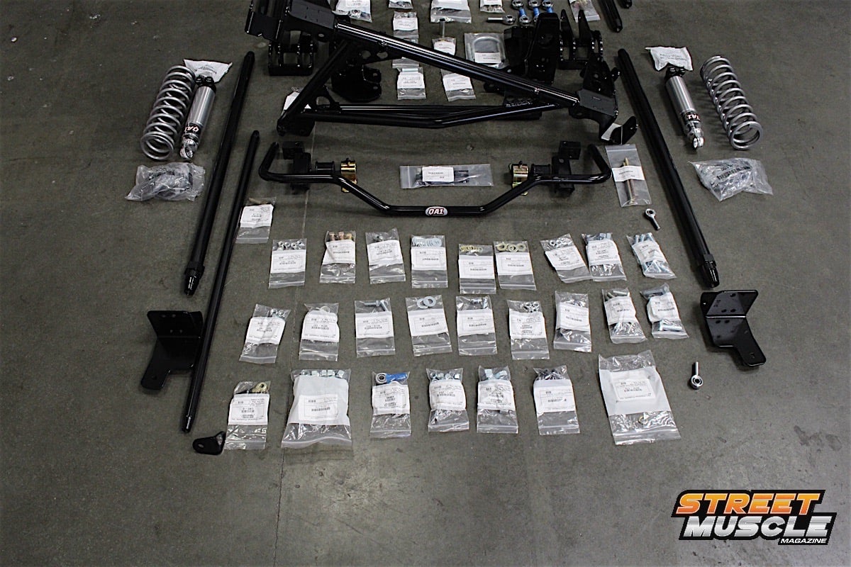
One of those products is available now: the Mopar Rear Suspension Conversion System [5], currently available for Mopar A-body cars, with additional applications planned for the future. This six-link rear suspension system eliminates the factory leaf spring, providing much better adjustability of the rear alignment, and pinion angles.
Because we’re upgrading the entire suspension for an A-body Mopar, we ordered the Level 3 handling kit (PN HK03-CRa1 [6]) from QA1. This kit includes front and rear suspension components, front and rear sway bars, double-adjustable front shocks, double-adjustable rear coilover shocks, front K-member, rear cradle, and all necessary hardware.
 [7]
[7]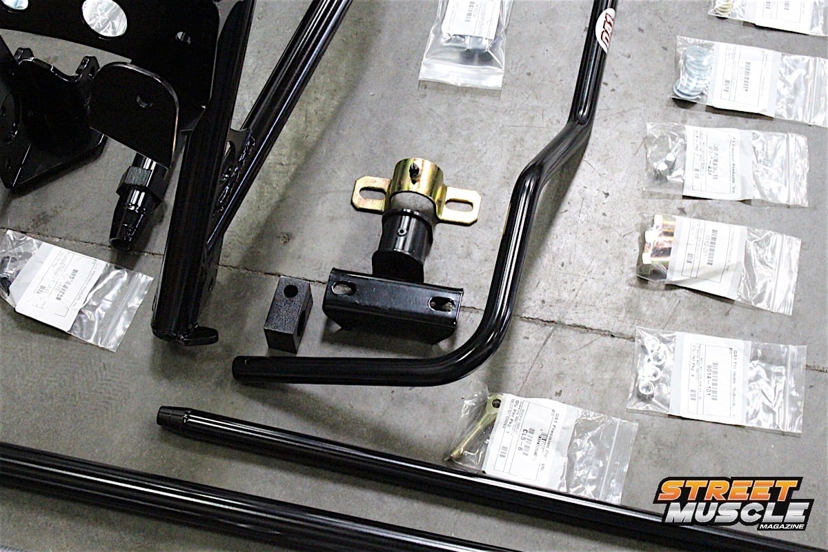 [8]
[8]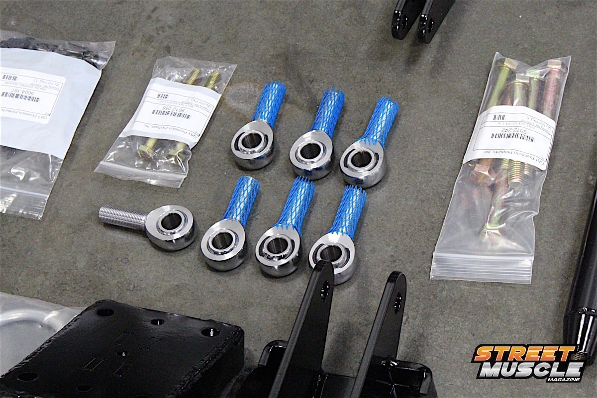 [9]
[9]
Did we mention that you get everything you need in this suspension kit? Everything is labeled, and it is wise to leave everything in its bag until that part is needed. You'll have a few dozen bags of hardware, so don't get ahead of yourself by opening the bags before you need to.
QA1’s Damien Brase told us, “Now that we have the first kit in production, it opens up the possibility for other vehicles by using this kit as a base and building on it for other Mopars, or even some GM applications.” We asked Brase what the target customer is for the Level 3 handling kit is. “This kit was designed with Pro-touring street cars in mind, we also wanted to make sure this is a bolt-in system that did not permanently alter the car should someone ever want to put it back to stock,” he said.
Introduced at the 2014 SEMA Show [10], the six-link rear suspension system [11] is a complete, bolt-in kit that requires minimal drilling, no welding, and can be installed in about a day or less, depending on whether you’re buying the pizza to get an extra set of hands on the kit. It utilizes factory mounting points on the rear body, frame rails, and factory spring perch locations, so there’s no guesswork or recalling your elementary school geometry lessons.
 [12]
[12] [13]
[13]
 [14]
[14]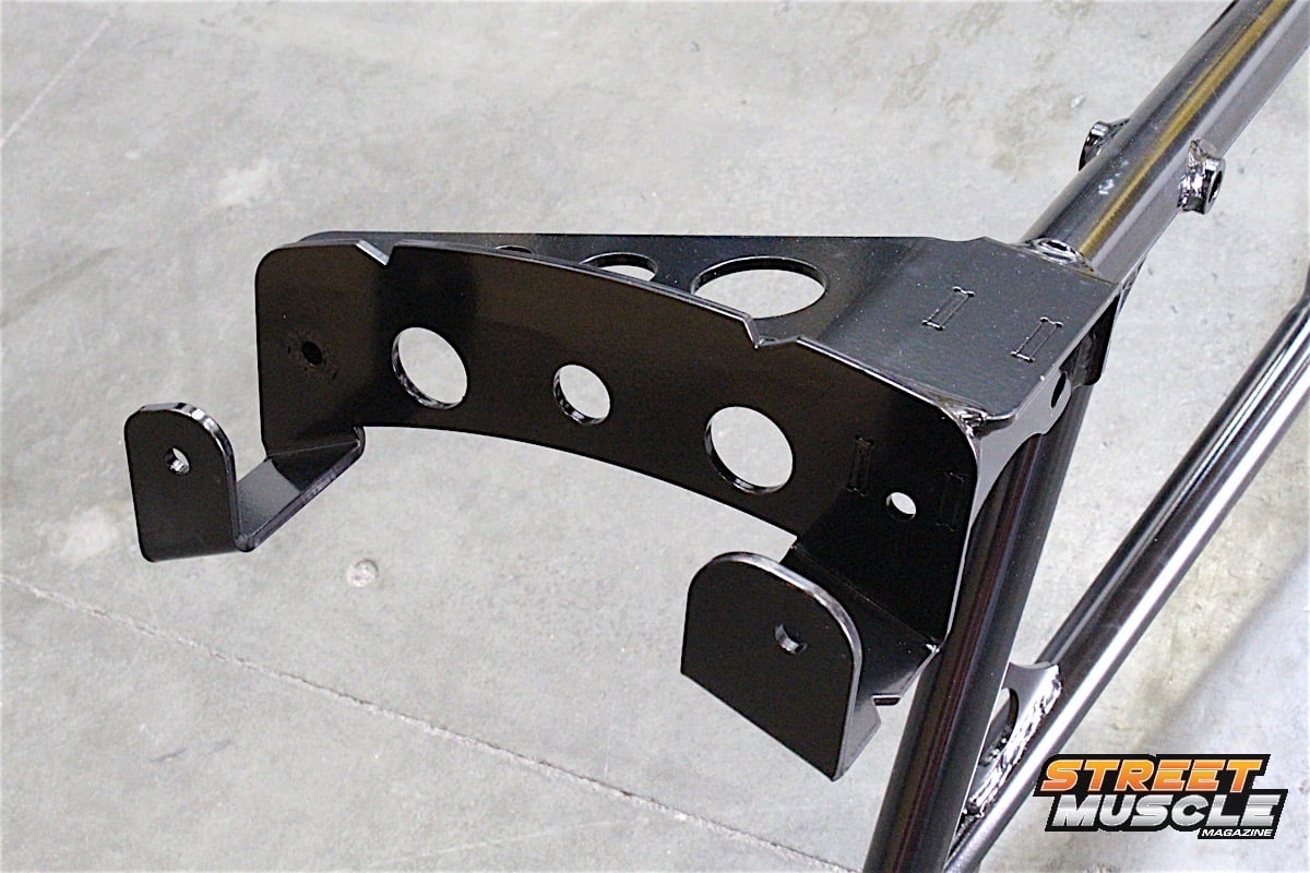 [15]
[15] [16]
[16]
Eliminating the leaf springs means that coilover shocks will need to be installed in this kit. With the additional strength of the cradle, the upper crossmember on the car will be able to support the additional weight, which is now centrally located above the axle.
One of our favorite Mopar performance shops, Viau Motorsports [17], was planning a build of a 1967 Dodge Dart. This Dart is getting the Viau treatment, meaning the car was stripped down to nothing but the shell, and every nut and bolt going back on the car is going to be a new part. The complete drivetrain, interior, and suspension are new, as well.
For this installation, we started with the new six-link rear suspension and will follow it up with the front installation, and then get the car down to the alignment shop and get a full, four wheel alignment, as well as set the pinion angle using the fully adjustable links. It would not make sense to bother with setting either of these (alignment or pinion angle) until the car is finished because in order to do so the car has to sit on the ground, with the full weight of the vehicle on the suspension.
 [18]
[18]Fresh out of paint and ready for some added muscle to the drivetrain, the 1967 Dart is a great candidate for a QA1 suspension upgrade.
Starting With A Fresh Canvas
The Dart came straight from the paint booth to the Viau Motorsports shop for the first step of its complete makeover: the rear suspension. It should be noted that this kit is designed to install on the factory 8-3/4-inch rearend with three-inch axle tubes. Because the links are connected to the axle housing via a bolt-on clamping system, it’s important to note that any modifications to the rearend width may cause fitment issues. The kit is designed to work with a stock width housing.
Viau used an empty 8-3/4-inch rearend housing built to factory specifications. The brackets that bolt to the housing are done so without removing anything from the housing, such as spring perches or brake tube retainers. As mentioned, a few holes needed to be drilled in the frame rails, but no cutting or welding was required.
 [19]
[19]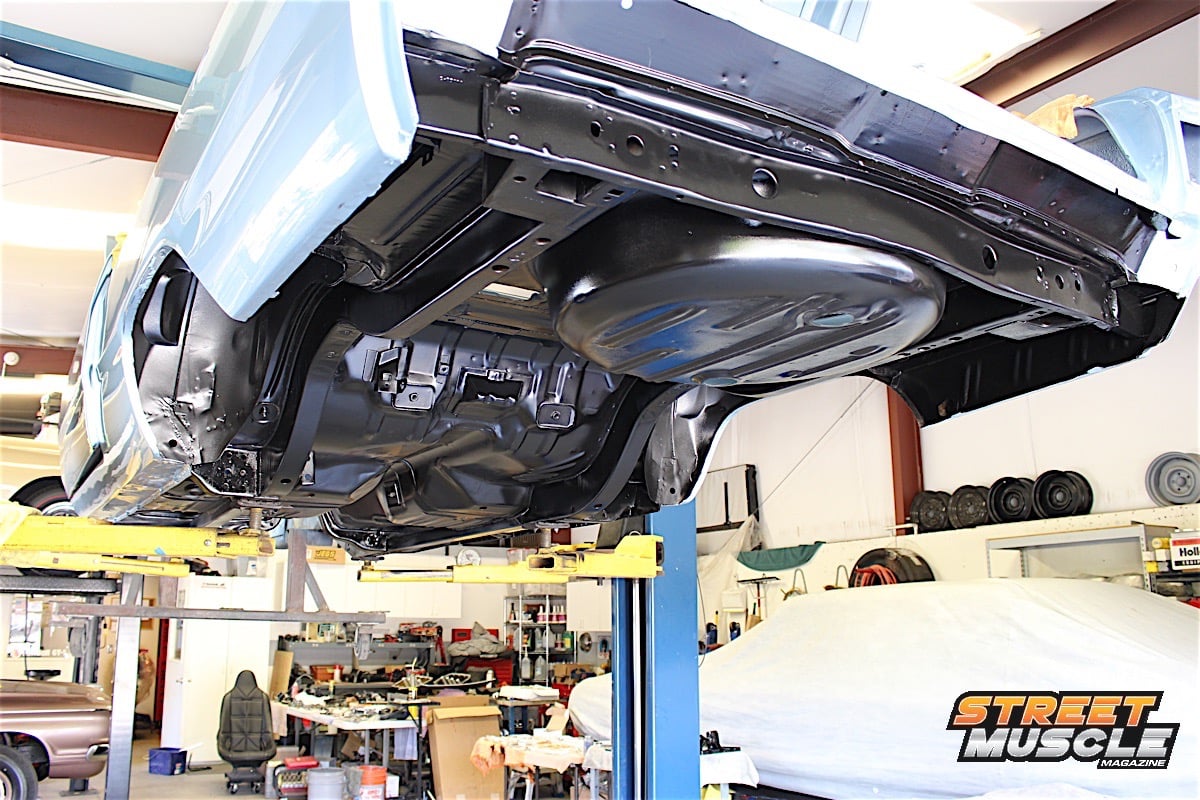 [20]
[20]
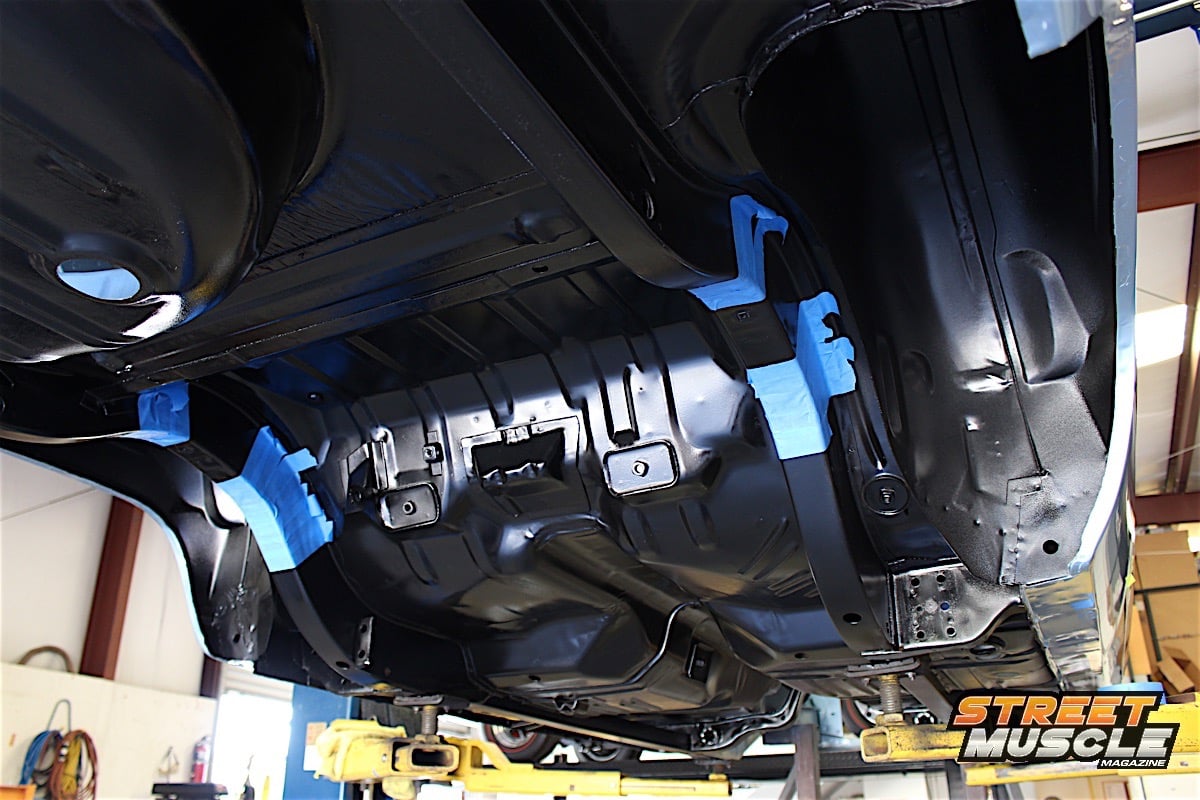
Viau Motorsports does things right, and the underside of the car was prepped and painted specifically for this suspension install. You can expect to see this car at bigger events once it's completed.
The main component is the cradle that mounts to the frame of the car and supports the suspension. It’s designed to attach primarily to the upper rear shock mounts as a strength member, and also to both frame rails.
The majority of the load on the cradle is going to be on the OE shock mounting locations. -Damien Brase, QA1

“The majority of the load on the cradle is going to be on the OE shock mounting locations,” Brase said. “The 3/8-inch bolts are not seeing much side loading, so the frame connections don’t need to be clamped down on the frame rails.”
We had some width differences on the Dart, so lead technician Aaron Bourdage fabbed up some spacers to allow a snug fit, but Brase did tell us that it wasn’t imperative to do so – it’s more of a personal preference.
 [21]
[21]
 [22]
[22] [23]
[23]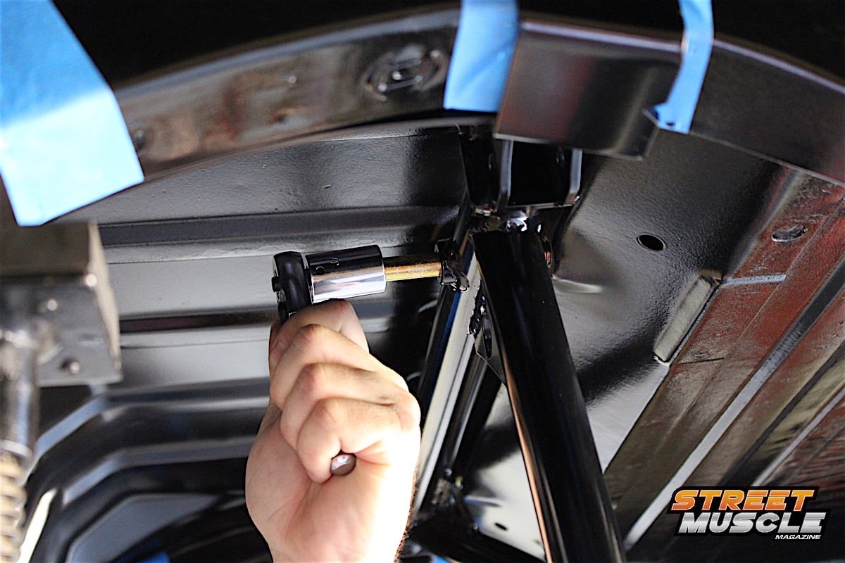 [24]
[24]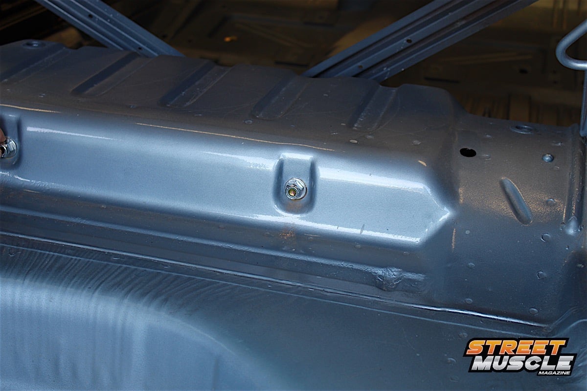 [25]
[25]
Care was taken to protect the frame rails from scratches upon initial install of the cradle. The two shock mounting locations receive bushings and will need to be accessed from the trunk area to install the nuts.
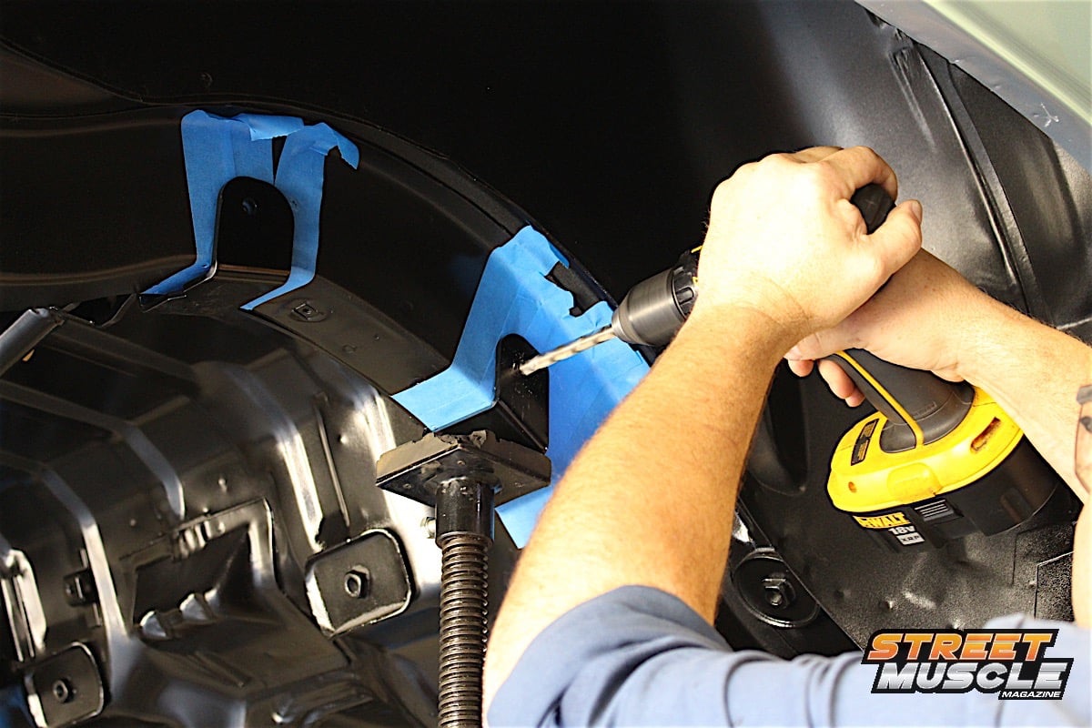
We used tape to protect the freshly painted underside of the car while we mounted the cradle for the first time. This was so that we could mark and drill the holes into the frame rails, but in order to line up the cradle properly, the two upper shock mounts needed to be removed, and a pair of supplied bolts and sleeves are used to mount the cradle to the upper shock mount location.
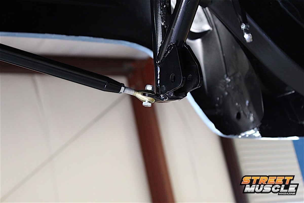
After drilling the holes in the frame rails, we removed the cradle to clean up the holes, clearing any debris or sharp edges. We also used a paint pen to dress the bare metal after drilling – just an added measure to help protect from rust. The cradle was then secured by attaching a rod to the rear bumper bracket which also keeps the lower panhard bar mount stable.
 [26]
[26] [27]
[27]
 [28]
[28]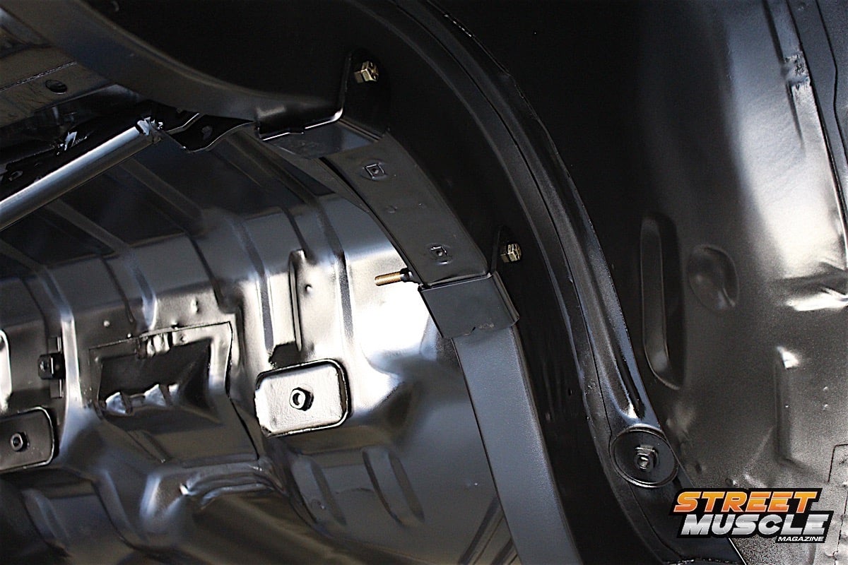 [29]
[29]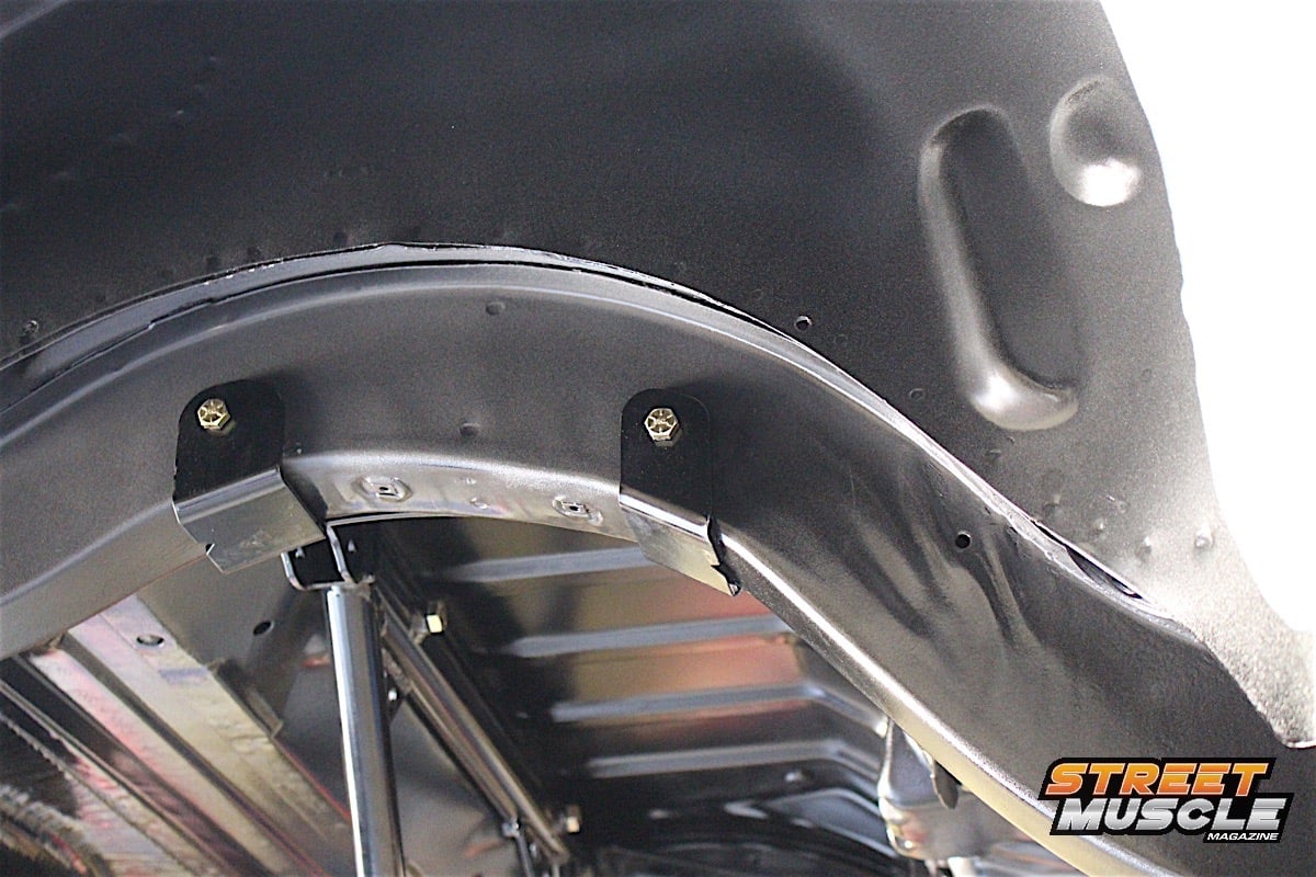 [30]
[30]
Because the cradle is secured at the upper shock mounts, there is very little side load on it. The cradle will mainly see compression loads and relies on the strength of the bolts.
We mounted the front and rear link brackets to the chassis in place of where the factory leaf spring brackets mounted. They utilize the existing body mounts, so no additional holes needed to be drilled for the rest of the install. Be sure to add the drop links for the rear sway bar at this time, the bolts will be long enough.
The axle brackets were attached to the axle housing at the spring perches, and are specific for right and left, so following the instruction here is crucial. Since this portion required torquing the four clamping bolts to 78 ft-lbs, having an extra pair of hands was a great help when torquing the bolts to spec.
Because we had the car on a lift, a tranny jack was used to raise the differential; doing so by hand would have made things a lot harder to do. This kit can be installed on the car sitting on jack stands, and using a floor jack and that pizza-eating friend to help guide the rearend into place will help tremendously – especially if the housing is fully assembled, carrying plenty of additional weight.
 [31]
[31]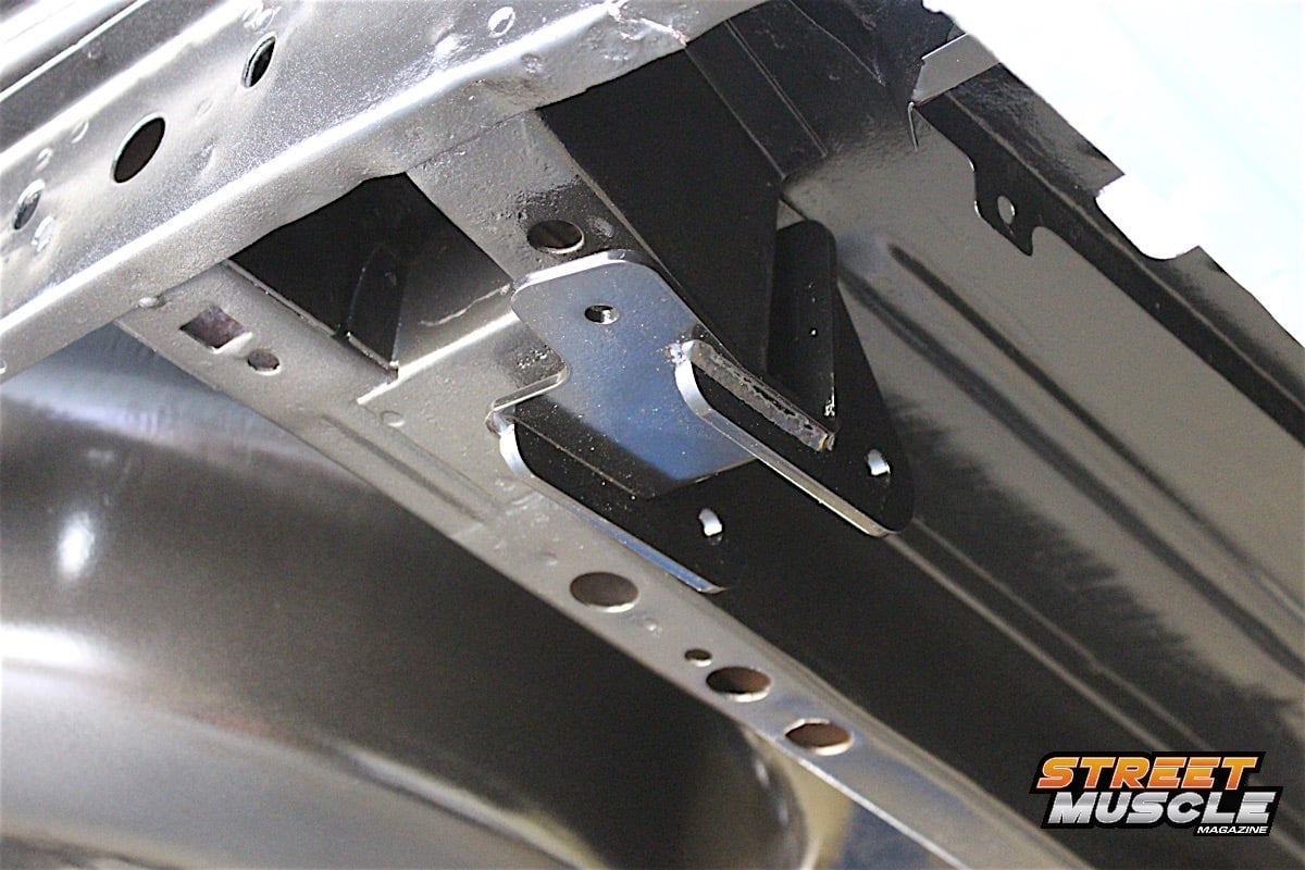 [32]
[32]
 [33]
[33]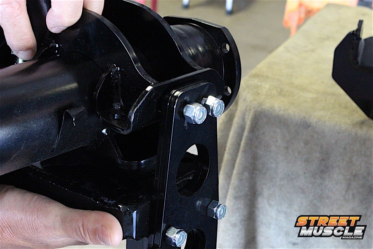 [34]
[34]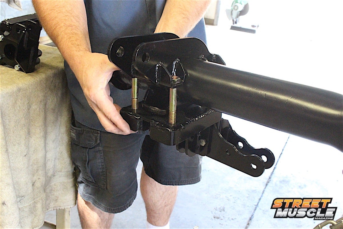 [35]
[35] [36]
[36]
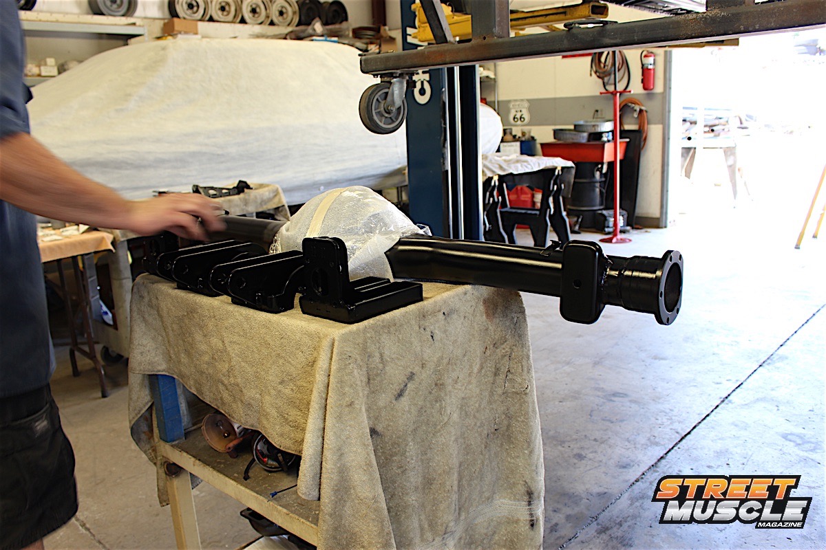
We were working with an empty housing because this is a fresh new build from the ground up. A complete assembly will not interfere with any components, but it helps to secure it to a bench or invite that friend over to make installation of the differential brackets much easier.
It’s important to note that the rearend needs to be supported for the full installation until the rear coilover shocks are assembled and mounted to the car. The shock absorber will prevent damage to the links and brackets by limiting suspension travel. A pivot bracket helps maintain pinion angle as the suspension compresses and extends. It’s important to be sure that during axle installation the pivot moves freely without the weight of the axle causing links to rest against their mounting brackets at maximum angles.
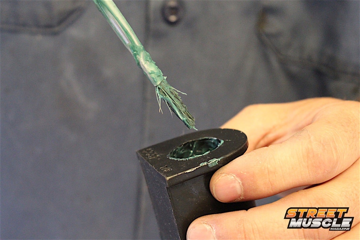
QA1 recommends to use anti-seize compound on all rod end threads, so when it comes time to assemble the links, a light coat on the threads of all rod ends is a good idea. These are self-lubricating and self-sealing components, and that means they are maintenance free. The links are all adjustable; one end will have a right-hand thread and the other will have left-hand threads, identified by a groove at the end of the link.
 [37]
[37]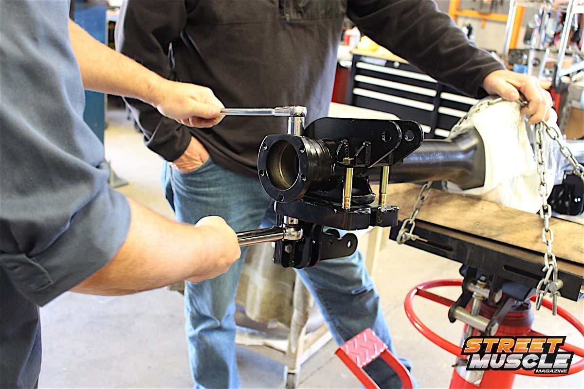 [38]
[38]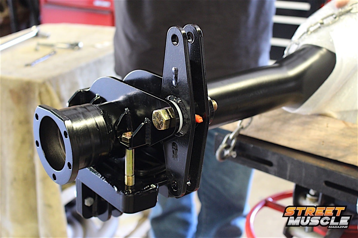 [39]
[39]
 [40]
[40]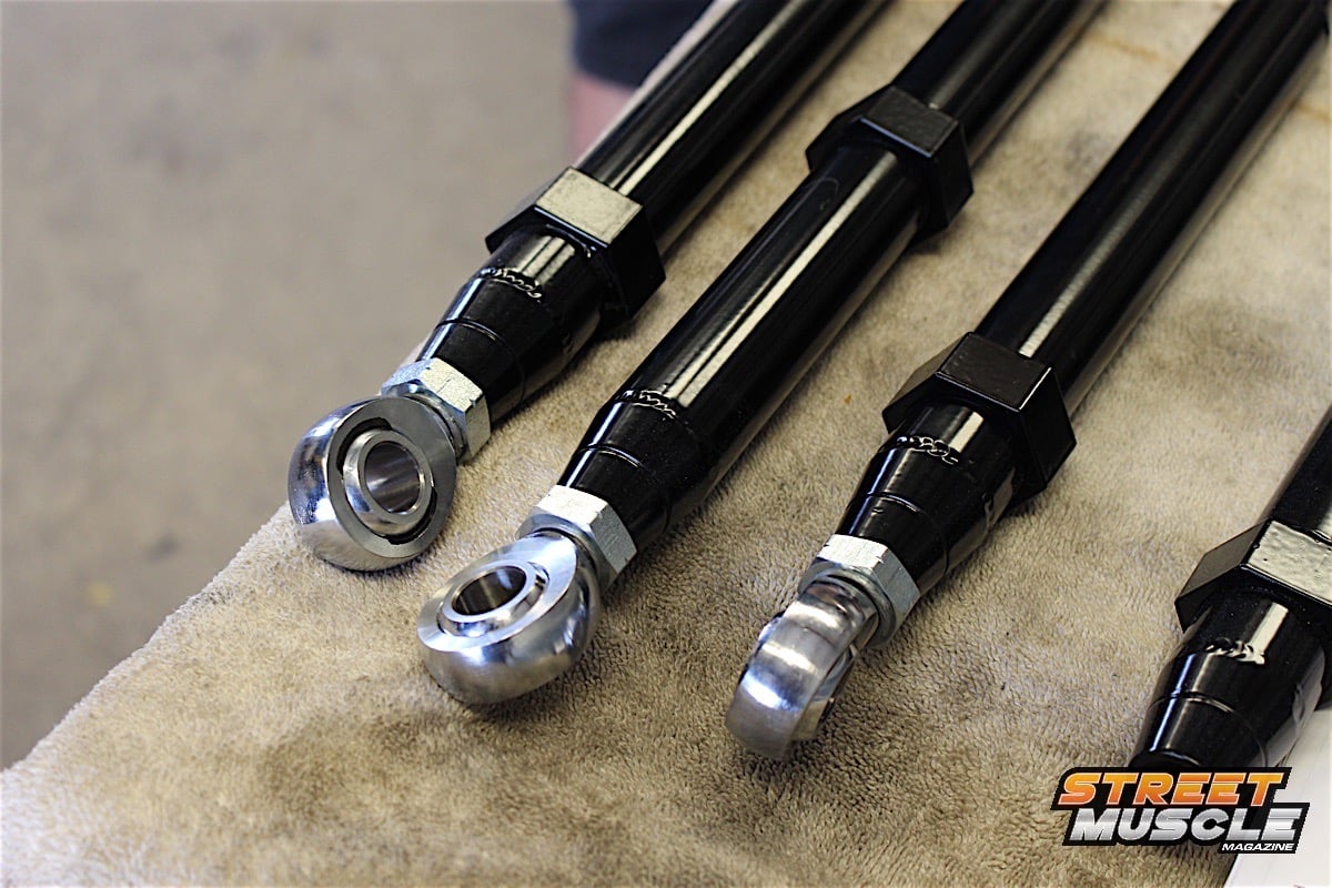 [41]
[41]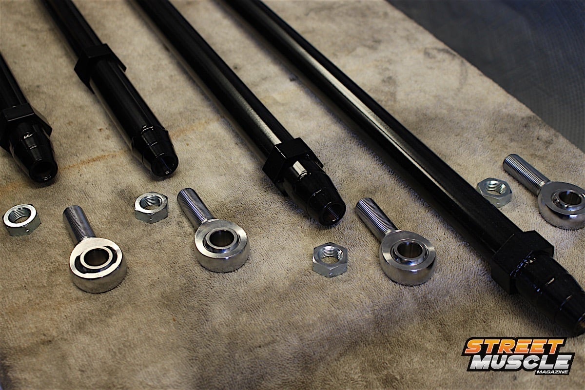 [42]
[42]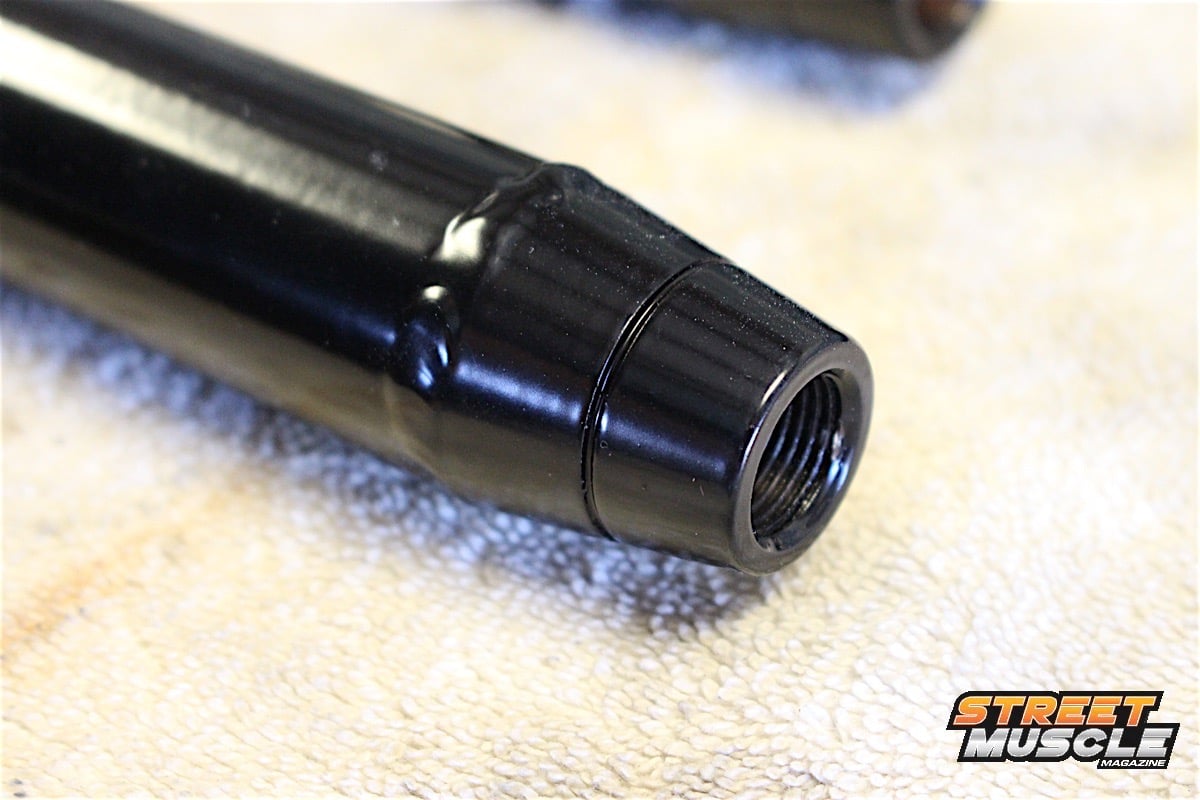 [43]
[43]
Don't forget to coat the rod ends, and keep in mind that each link will have both a right-hand and left-hand threaded end. The groove at the end will identify the left-hand thread (bottom right).
There are four links to the front, and a pair to the rear of the axle, each with a specific length. We kept the jamb nuts loose to allow us to make adjustments in length as we installed the links. It’s not necessary to be concerned with pinion angle during installation, that adjustment will require the car being at ride height, with the engine and transmission installed.
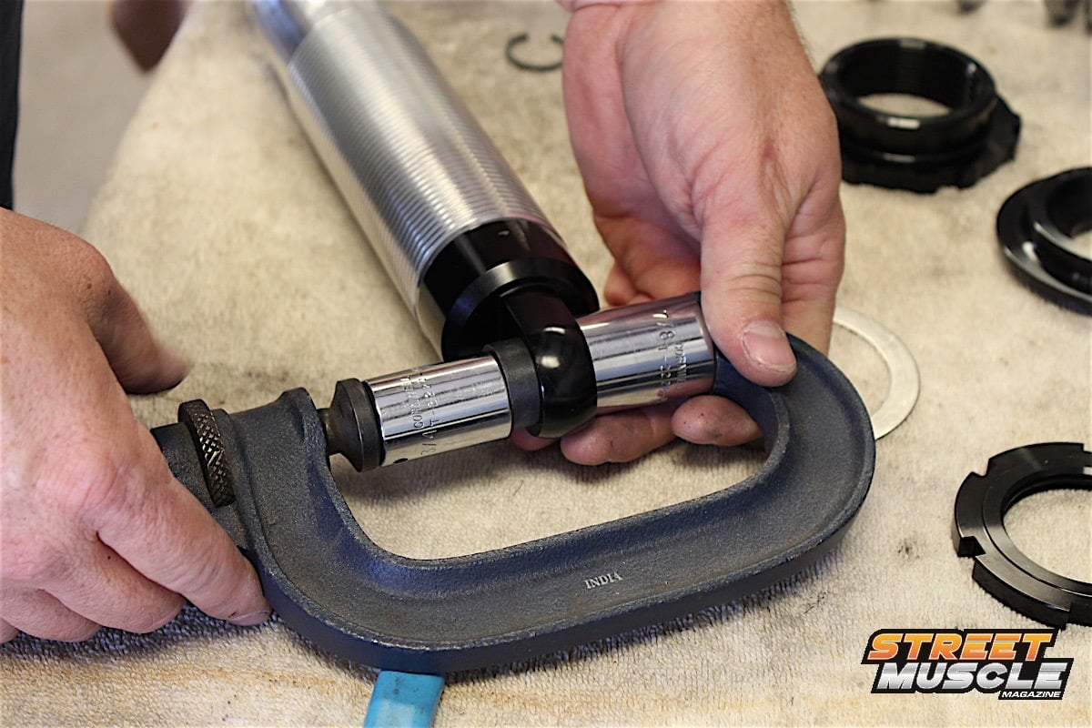
The coilover shock body required anti-seize compound to the threads, and failure to do so can void your warranty. This keeps the jamb nuts from binding when they’re turned on the shock body as the ride height is adjusted. Brase said, “The A-body six-link kit is designed to allow for a 26-inch fender height with 27-inch tall tires, with a one-inch height adjustment in either direction.”
 [44]
[44]
 [45]
[45]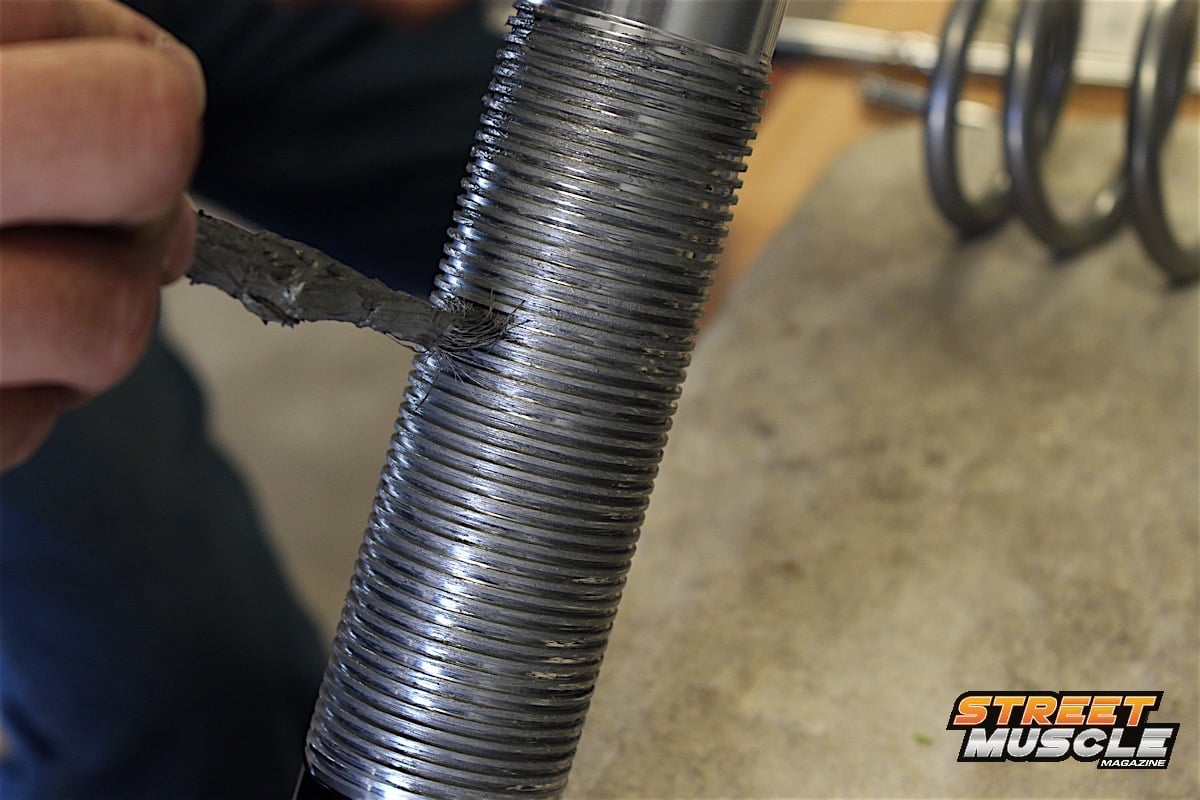 [46]
[46]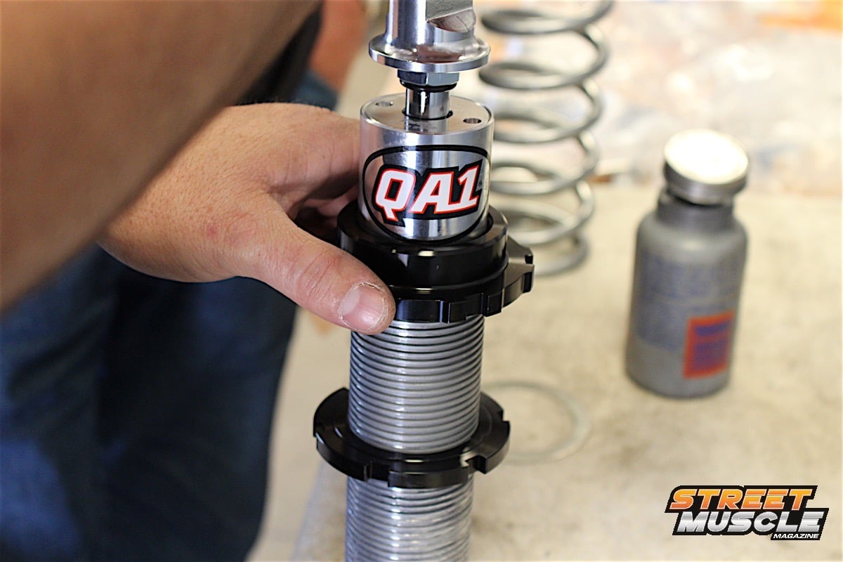 [47]
[47]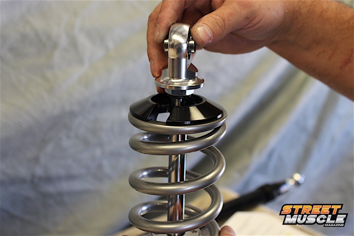 [48]
[48]
Anti-seize compound on the threads will make later ride height adjustments much easier. Skip using it, and it will void your warranty on the shocks.
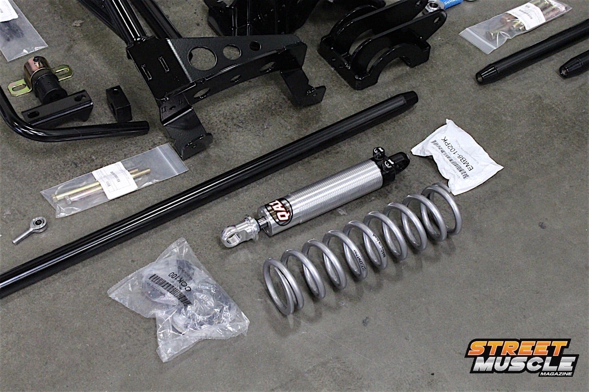
Available spring rates for this kit are 170 lbs./in. for soft, 200 lbs./in. for medium, and 220 lbs./in. for firm. QA1 does offer different spring rates from 80 lbs./in. up to 600 lbs./in., and customers can request different spring rates at the time of ordering. Brase said, “The six-link kit is also offered with QA1 single-, double-, or Quad-adjust shocks.”
Assembling the shocks is a simple procedure; we didn’t need a spring compressor to install the springs to the shock body. The jamb nut is installed first, then the lower spring perch and a shim that also required a coating of anti-seize before the spring is installed over the shock body. These shocks work on oil pressure, not gas pressure, so adjusting the knobs to the softest setting allowed us to extend the shaft far enough to install the upper spring perch.
 [49]
[49] [50]
[50]
 [51]
[51]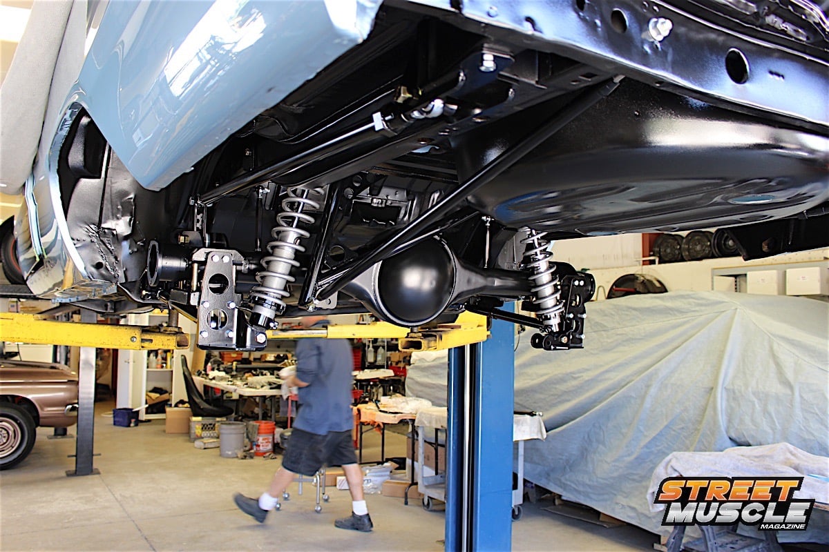 [52]
[52]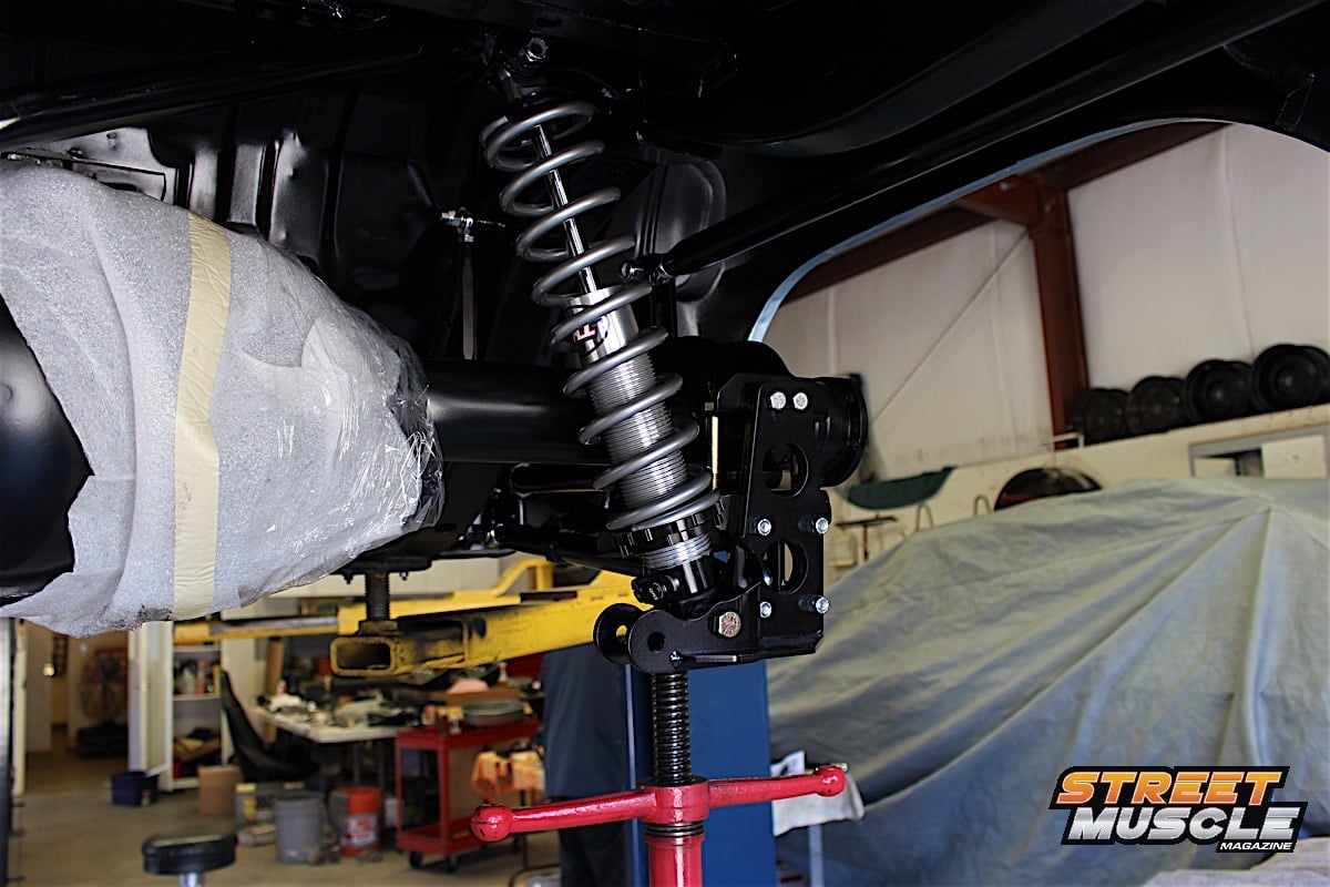 [53]
[53]
With both coilover shocks installed, the final steps could be performed: installing the panhard bar and the rear sway bar.
The spring was then inserted with the upper perch installed, and finally some adjustments were made so that the spring perches sat snug against the coil spring. Until the vehicle is on the ground, ready to go, adjustments are unnecessary. The adjuster knobs were located to the inside where they are accessible to make compression/rebound adjustments.
Coilover Shock Settings
Brase gave us the following suggested settings for both single- and double-adjustable shocks:
| Single-adjustable | Double-adjustable | ||
| Compression | Rebound | ||
| Drag racing | 4-10 clicks | 0-6 clicks | 4-10 clicks |
| Nice ride and handling | 0-6 clicks | 0-6 clicks | 2-8 clicks |
| Firm ride and improved handling | 6-12 clicks | 6-12 clicks | 8-14 clicks |
| Aggressive handling | 13-18 clicks | 13+ clicks | 14-18 clicks |
The suggested settings are simply to get you started. Curb weight of the vehicle, driving style, spring rates, and road/track conditions are all factors when it comes to making final adjustments to shock absorbers. Brase said, “All shock adjustments should be made starting at the softest setting and count the clicks up from there. Our guidelines will give a general range to start in, then the user can adjust up or down from there depending upon the ride or handling characteristics they are looking for.”
 [54]
[54]Adjustments can be set as a starting point, but many factors will affect the performance of the shock. Adjustments will need to be made up or down based on several factors, and with two knobs we expect to have our work cut out for us.
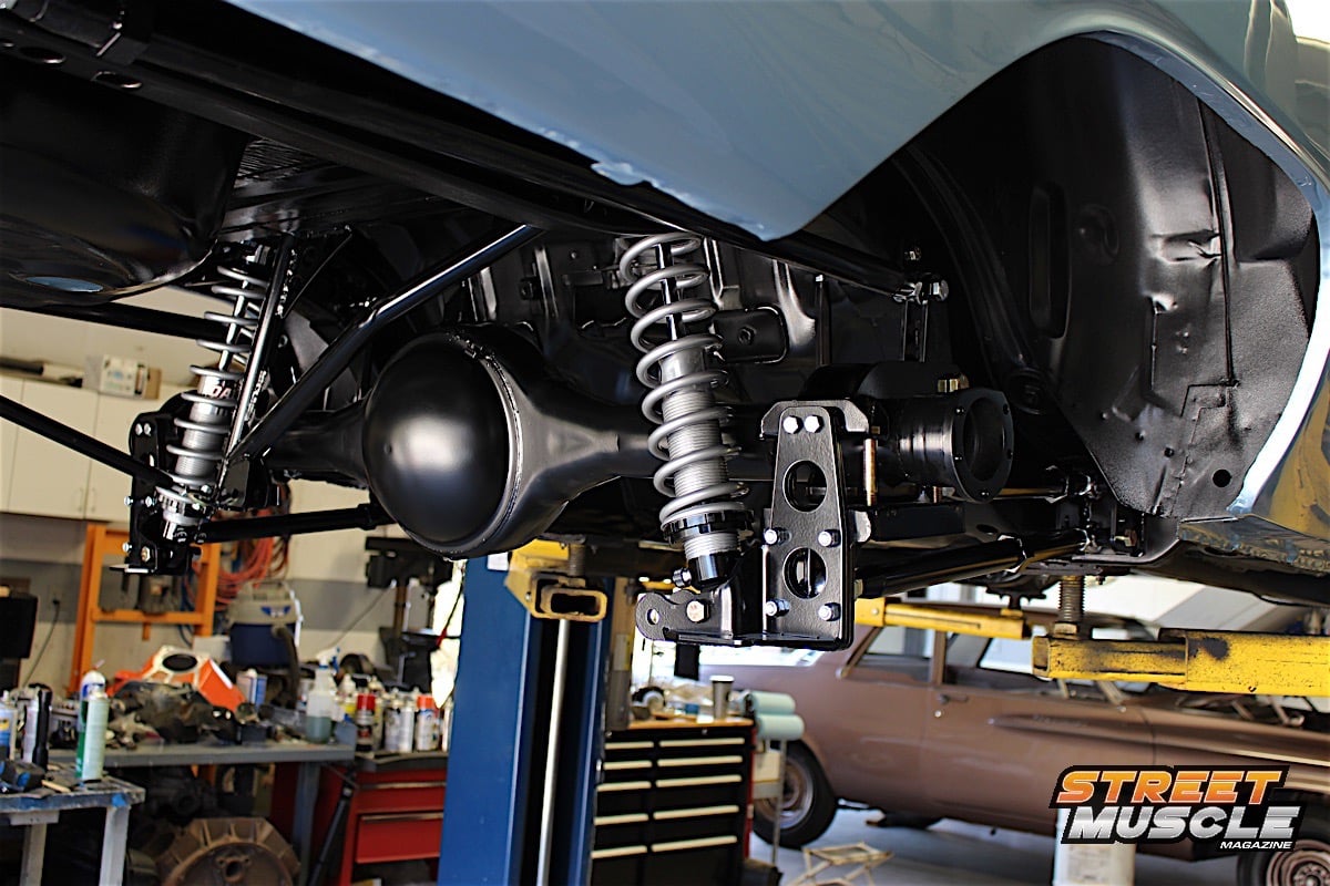
The panhard bar attached to the bracket on the differential and connected to the drop-down on the cradle. It may be necessary to bend the flange on the factory gas tank for clearance. The panhard bar is also adjustable, but will need to be done when the alignment is done, centering the rear axle on the car. The only thing left for us was the rear sway bar which mounted via clamps to the axle housing, in typical fashion.
We lubed the bushings for the sway bar, and used the measurements provided in the instructions to center the sway bar on the differential. Though this can be eyeballed, keep in mind there’s a lot going on with multiple links, exhaust, and shocks, so using the given measurements means mounting the bar once, and leaving it.
With the complete rear suspension kit installed, normally the ride height can be adjusted and the pinion angle set. Since we have six adjustable links that will affect the rearend alignment, getting the correct settings requires a trip to the alignment shop once the car is completed. Ride height should never be set with the car in the air, or without the car being road-ready. The same applies to pinion angle, if the car is still being built you’re simply wasting your time trying to fine tune these adjustments.
 [55]
[55]
 [56]
[56]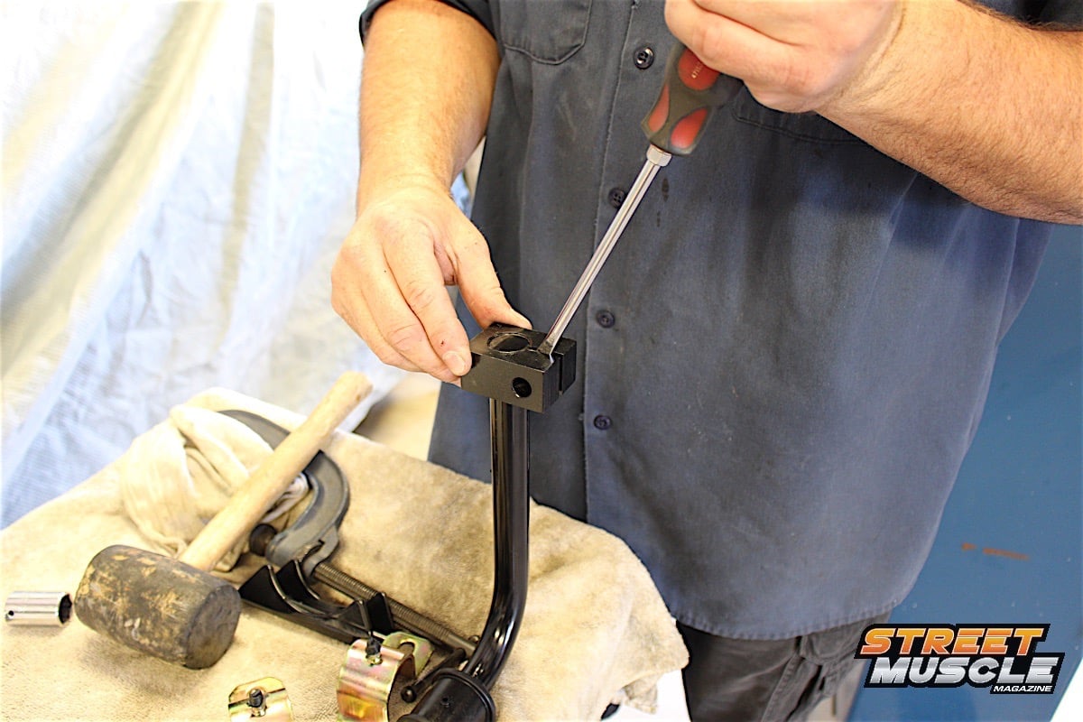 [57]
[57]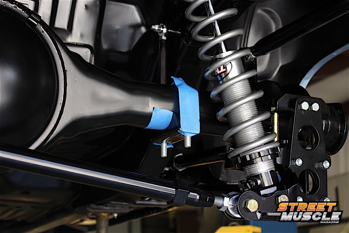 [58]
[58]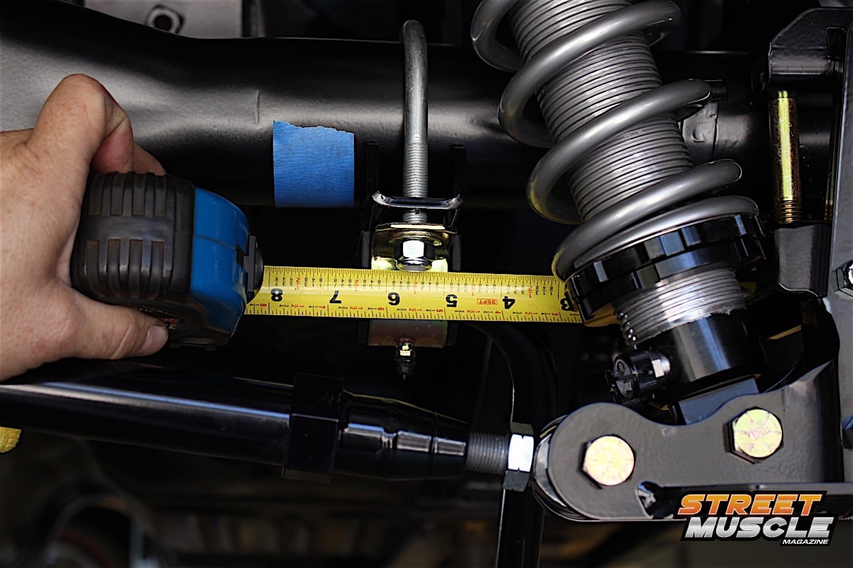 [59]
[59]
We used the measurements provided by QA1 to center the rear sway bar to the axle housing. Misalignment could create uneven stress on the sway bar which would cause it to shift.
Ride Height And Pinion Angle Settings
When the car is completed, we’ll head to the alignment shop. Brase told us, “The rear ride height should be adjusted first. Then the front lower links should be adjusted to set the wheelbase along with the panhard bar to square the axle in the car. Once the wheelbase is set and the axle centered under the car, the pinion angle can be adjusted. Either lengthen or shorten both the front upper link and the rear links to adjust the pinion angle. These links should always be adjusted together.”
A race car should have the setup done with the driver or at least the simulated weight of the driver in the driver’s seat to help get a neutral handling car. -Damien Brase
It should go without saying that anytime an adjustment is made, the alignment and the pinion angle should be checked again. Brase also suggests, “With the amount of adjustability this system allows, the car should be tested and have the bolts and jam nuts checked for tightness after about 50 miles.”
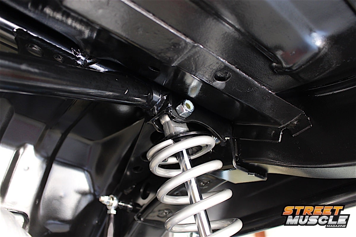
 [60]
[60]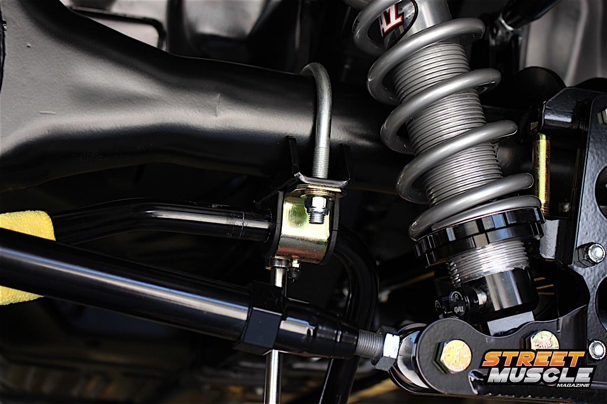 [61]
[61]
It's a tight fit, but everything was engineered to fit into place like a jigsaw puzzle. This kit adds some brawn to the A-body rear suspension.
We’ll bring back the Dart for the front suspension installation in the coming months, and then follow up with the alignment process and a couple of track runs later this year. For now, Viau Motorsports is getting the rest of the car put back together in between suspension upgrades, and the engine and manual transmission are about ready to be installed as well – but they will go in when the QA1 front K-member is installed.
You can find these products on the QA1 website [3], where you can order your suspension kits in stages [62], or as a complete kit for front and rear as we did with this Dart. With the minor exception of some specialty tools to remove torsion bars and ball joints on the front suspension, QA1 designed these kits so that the hobbyist with some mechanical ability can install them in their own driveway or garage. We completed this install in less than a day, taking our time to document the process for you.
 [63]
[63]
 [64]
[64]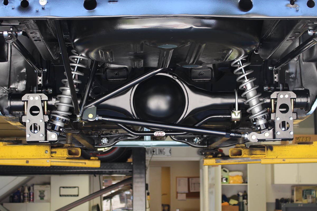 [65]
[65]
The Dart already looks like it's ready for action – but it's got a long way to go and a short time to get there.