 When the engineers at Chevrolet designed the Camaro almost 50 years ago, they couldn’t have imagined the high performance conditions the F-body cars would be subjected to today. As the decades have rolled on, so has automotive technology. While the first-generation Camaro is still able to hold it’s own in the drag race arena, Chris Alston and his gang at Chris Alston’s Chassisworks thought it might be time to bring 2015 technology to 1960’s muscle. The result was a stunning lightweight and completely bolt-on tubular front clip for 1st Gen Camaros and 2nd Gen Novas. We were able to sit in with Chris Alston Sr. and his team for a peek into the design and manufacturing processes behind this front end.

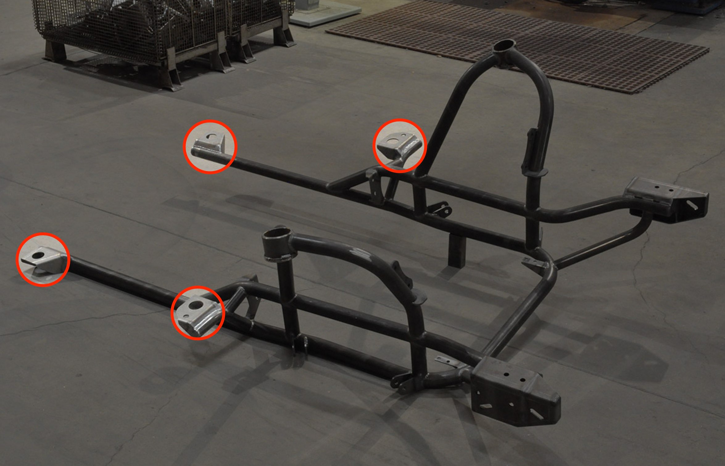
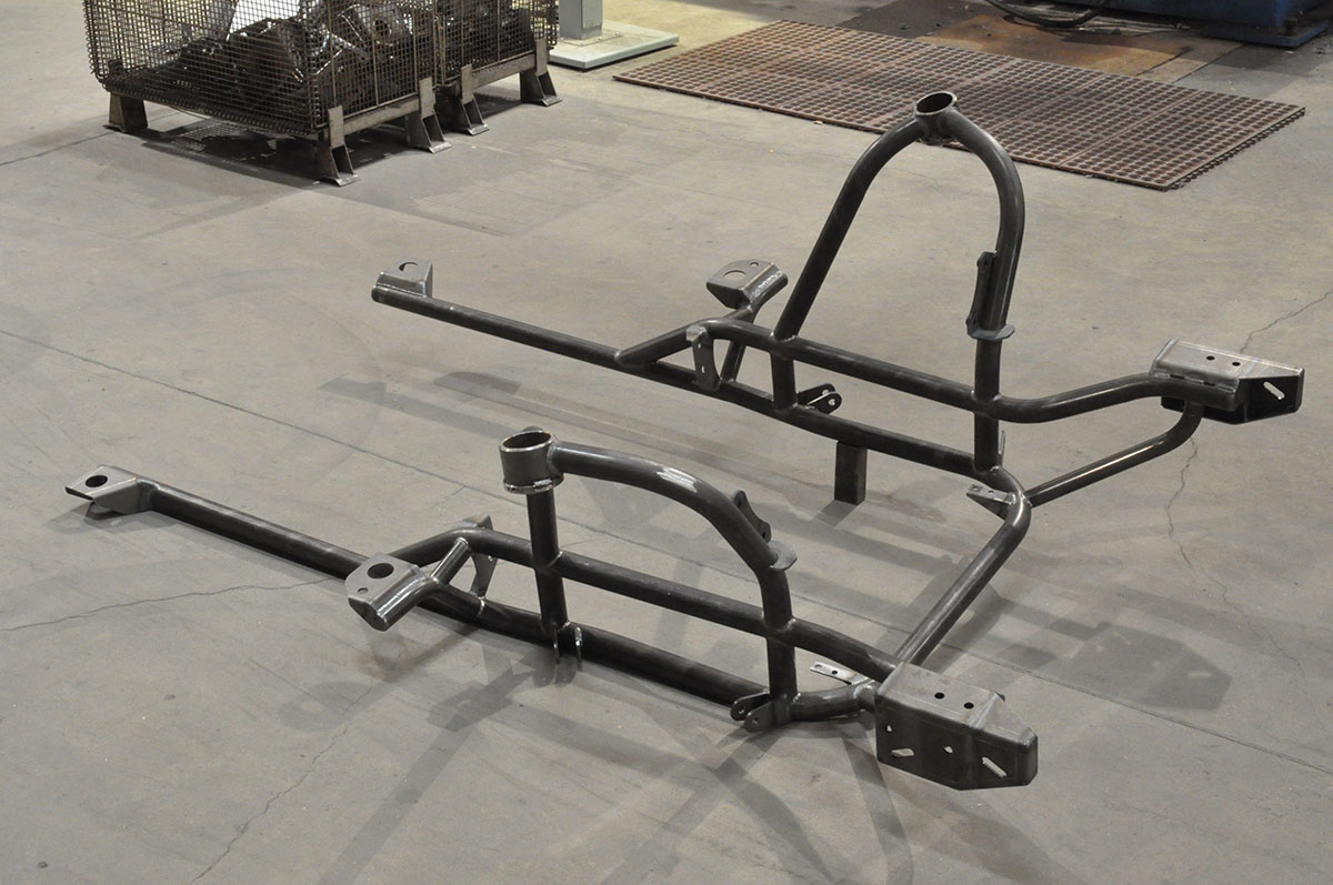
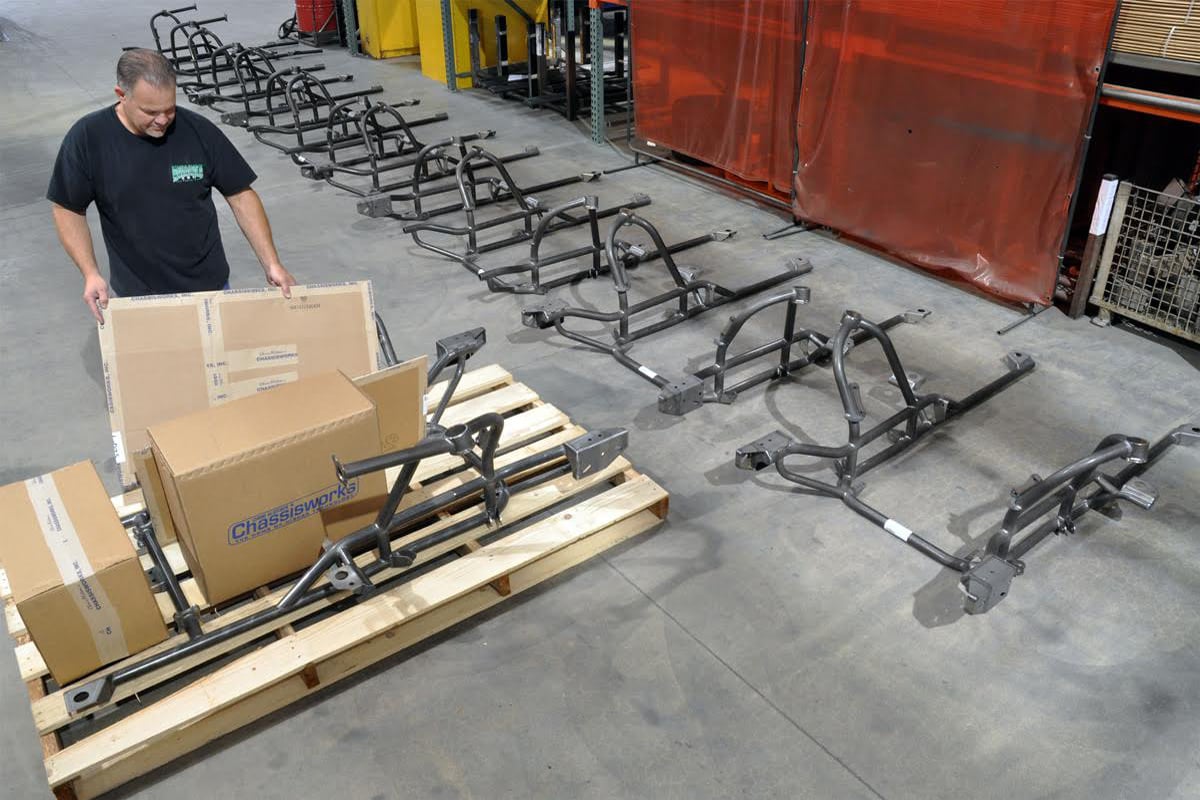
Chris Alston's Chassisworks new strut front clip for the 1st Gen Camaros and 2nd Gen Novas (left) is loosely designed on the already popular strut front end replacement for 1st Gen Novas (right).
Chris Alston Sr. explained, “Since we already build a similar front end for 1st Gen Novas, we already knew how to make a lightweight strut setup work for early model vehicles. After reviewing the project board at the shop, we decided it was time to provide a quality front end suspension for early Camaro racers.”
It Bolts In?
Due to the unibody design of early Camaros, Chassisworks was able to design the front clip as a complete bolt-in replacement piece. In simple terms, after removing the OE subframe, the aftermarket front clip is reattached using four 5/8-inch bolts.
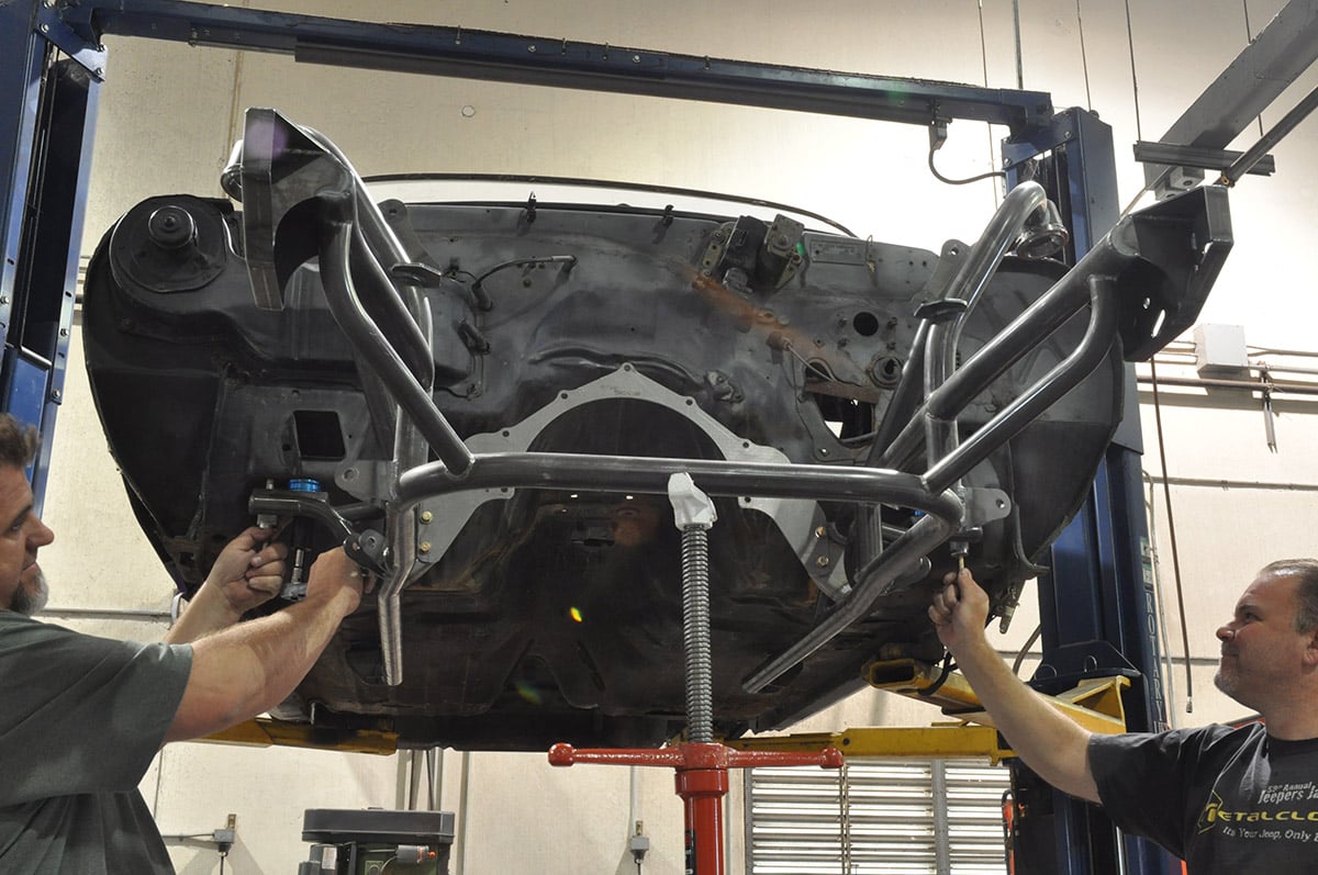
Early Camaros utilize a unibody chassis and as a result, the OEM front clip is held in by a mere four bolts. The Chassisworks front clip uses these same four bolts for installation. Further support is provided by the supplied front strut bars that are typical in most roll cage installation kits.
Chassisworks also supplies the two forward strut bars, normally found in 12-point roll cage kits, to tie the front clip into the existing roll cage. Even though the front strut kit is a bolt-in replacement, Chassisworks considers it a drag-race only part, and doesn’t recommend using it without tying it into the roll cage with the strut bars. The installation demonstrated by Chassisworks in this story utilized an optional bolt-in front strut bar. The upper support strut-bar is included and can be installed as a continuous tube from the strut mount to the cage side, or as a two-piece support with a bolt flange at the firewall. We opted for the bolt-flange option, allowing easier removal of the clip if ever needed.
The kit’s bolt-in status is further bolstered with fabricated frame horns that accommodate the original core support and sheet metal. The horns and supporting bars are optional. The reasoning behind this is many racers today forgo the core support and mount composite body panels using custom fabricated mounts.
From the beginning of the project we wanted to meet several goals and nothing was going out the door until they were met.

What’s In The “Box”?
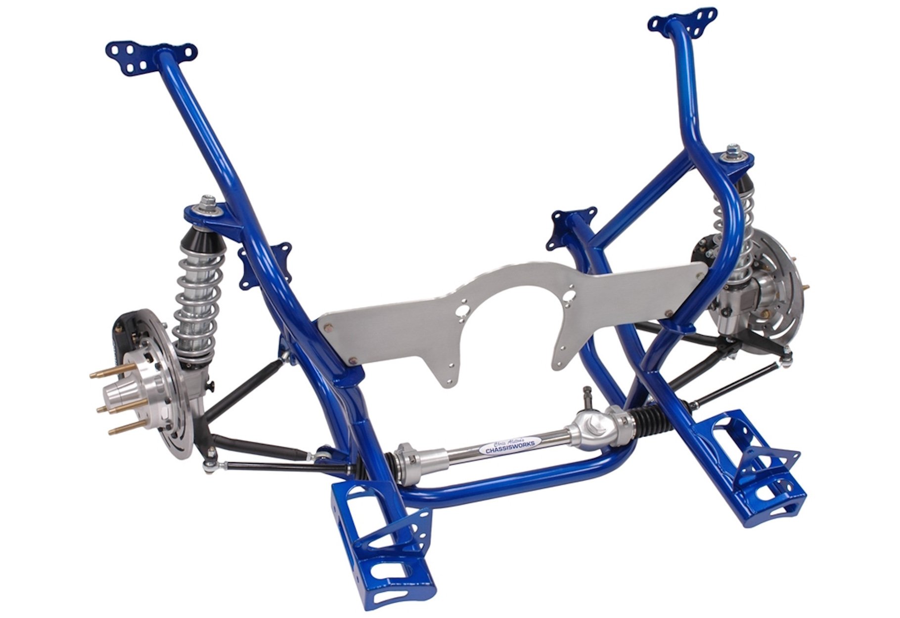
The kit as provided by Chassisworks, comes with everything required for the conversion, and includes the frame clip, double-adjustable billet VariStruts, tubular control arms with 4130 rod ends, a billet-aluminum drag-race rack with extended-travel, billet rack clamps, bumpsteer adjustable tie-rod ends, and a complete disc-brake set with billet hubs, lightweight rotors and aluminum calipers. As Alston noted, “It would be easy to break this kit up into many smaller kits to make it look cheaper, but we don’t like fine print or hidden costs. We want to make sure the customer is provided with everything they will need to get back on the strip after the conversion.” After installing the frame, the remaining components for installation include a steering column, brake lines, and the drivetrain.
Where It Started.
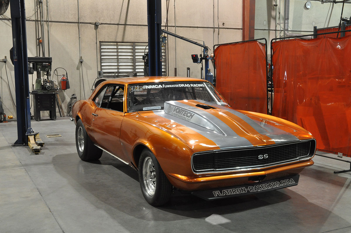
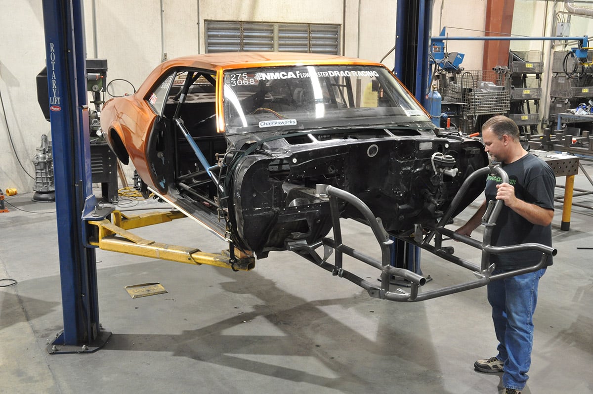
Our 1968 drag radial Camaro as is sits before installation of the Chassisworks strut clip. We removed the engine and drivetrain prior to sending the car to Chassisworks.
The project started with NMCA Outlaw Street racer DJ Reid’s, Vortech inspired, 1968 drag radial Camaro. The Camaro is a stout combo that is capable of running 4-second 1/8 mile, and 7-second 1/4 mile blasts. However, the conventional 412-inch small block it sported was not going to be enough to face proven competitors like Artis Houston, James Lawrence, Armen Maghdessian and Eric Gustafson. The team realized at the end of the 2013 season that changes had to be made. Those changes meant renovating the drivetrain with LSX hardware. The seasonal break-in racing provided a perfect window of opportunity to explore Chassisworks’ new front clip.
Design And Manufacturing
Designing a completely new front subframe and suspension from scratch is hard. Meeting the dimensions of a nearly 50-year-old vehicle is even harder. However, Chassisworks didn’t stop there. They worked to make their front end lighter and more performance oriented.
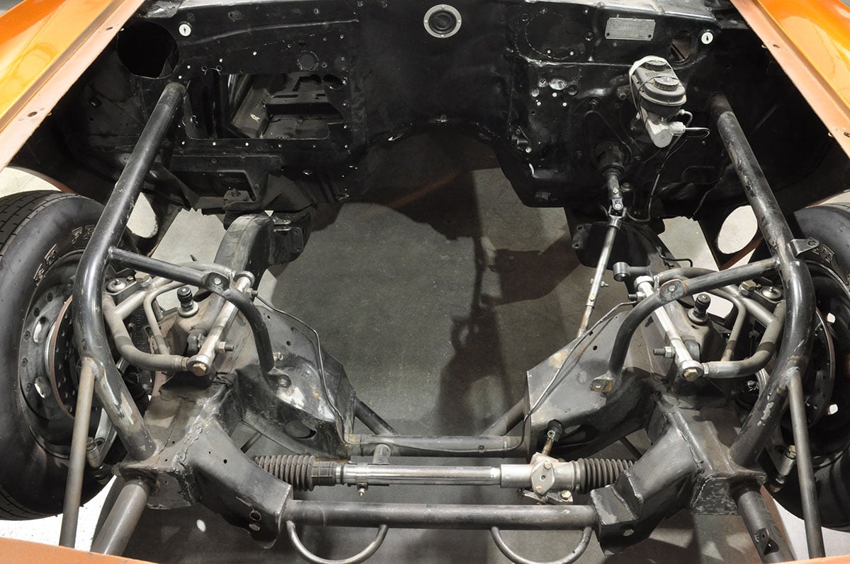
We are removing an OE subframe modified for a rack and pinion, and support struts. Changing over to the new strut clip will reduce overall weight, while freeing room for easier engine accessibility.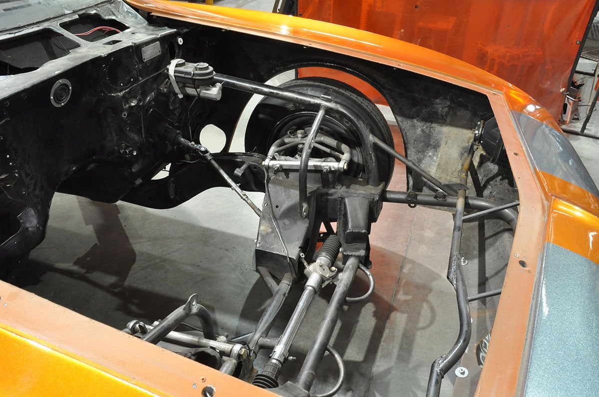
“It had to be light, it had to use top quality components like our in-house manufactured steering rack. Most of all, it needed to be a performance replacement that could bolt in to the OE location while accommodating all the OE panels and supports.”
Everything at Chassisworks, from design to manufacturing, is state of the art, and this project proved to be no different. As part of picking up a new front clip, Chassisworks provided a first hand account of how they designed, manufactured, and then assembled this kit.
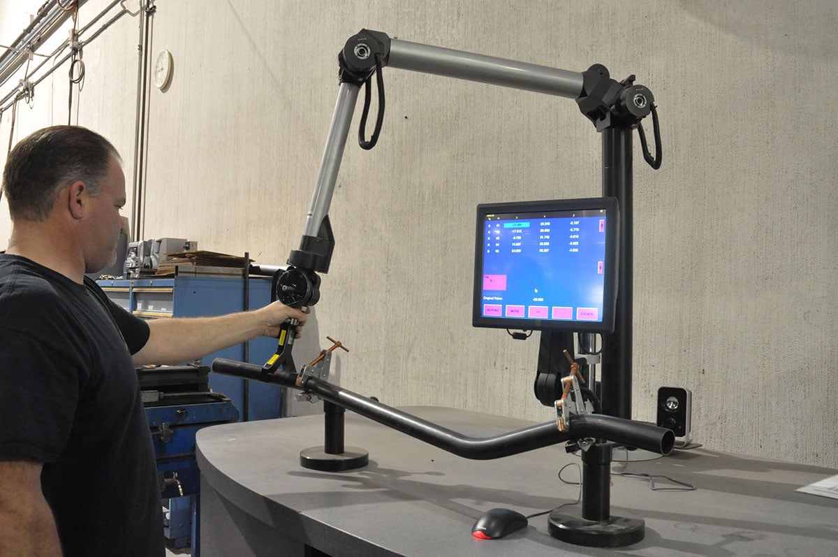
As Sr. told us, “The first step in the process is to get everything digitized into the machine. From there we can map critical points that will allow us to design a prototype that will use OE mounts, while remaining unobstructed by the chassis.”
The Chassisworks R&D technique is unique, because the shop uses software to design their components prior to burning any tungsten or cutting steel. They digitize everything, and it is all done in house. This process allows them to scan and render vehicles for desktop design using their CAD software. Chassisworks scanned the exterior and interior portions of a stock 1969 Camaro, and then combined them in the software. Once completely rendered, Chassisworks digitally constructed the front clip in a virtual environment.
This process included designing the strut frame and associated suspension pieces, including lower A-arms and strut integrated spindles. In addition to providing a solid design environment, the software is also used to perform stress analysis, and check for potential clearance issues.
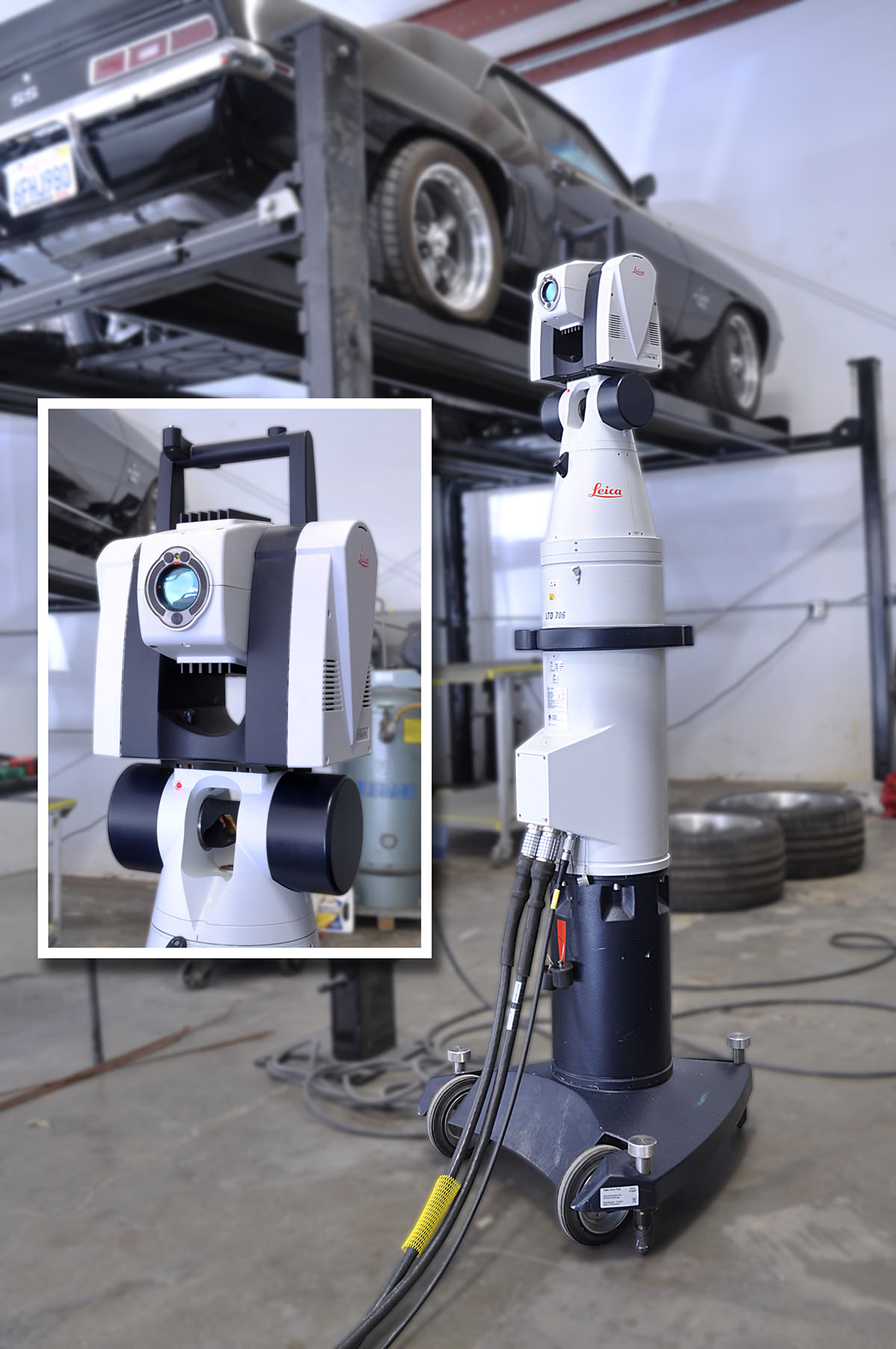
Before Chassisworks officially made the decision to build a strut clip for the first-generation Camaro they scanned a vehicle for other projects. This particular scanning system uses a stationary tracking base with an articulating head to follow a handheld laser scanner.
Not everything takes place on the computer, Chassisworks is a full-manufacturing facility with several CNC-operated machines. One of the most intricate parts of the frame building process is the core-supporting frame horn option.
“We’re really happy with how the frame horns turned out. We send 4130 sheet metal through a CNC laser, and then through a bender to make a highly articulated piece that meets OE mounting specifications. Stock core support? No problem.” Alston Sr. commented.
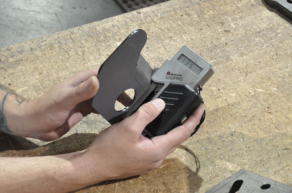
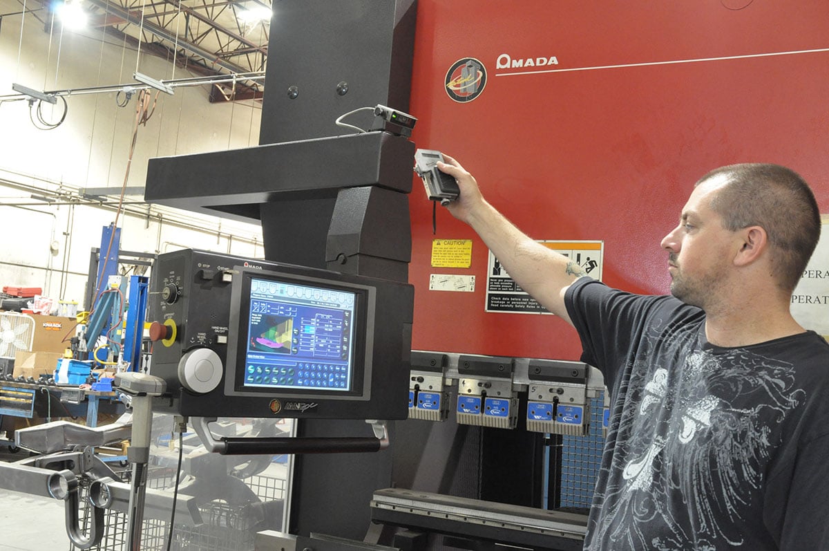
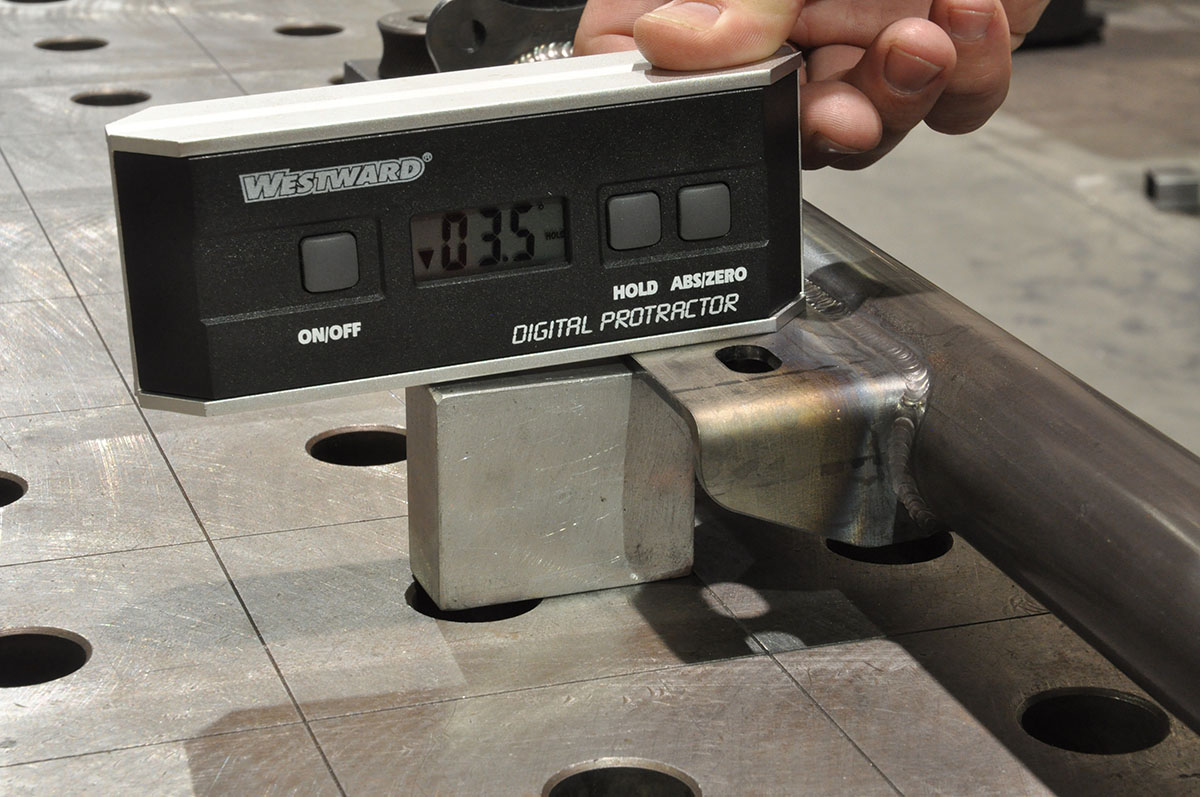
The frame horn starts as a flat sheet of 4130 steel that is cut on a laser CNC. The cut part is then placed in an extremely precise Amada press brake for bending. The machine is equipped with a digital gauge that transmits the measurement back to the control software where minor corrections in the bend program are made. This ensures subsequent parts are within tolerance. Once the bends are made, a completed part is ready for welding. After the plates are welded together, the frame horn is then welded to a reinforced tube that extends from the main clip. In keeping with their objective of 100-percent OE compatibility, the frame horns include OE core support holes and the OE bumper mount provisions.
The effort put into engineering and parts accuracy pays off by eliminating the need for fixtures in some operations while maintaining finished assembly accuracy.
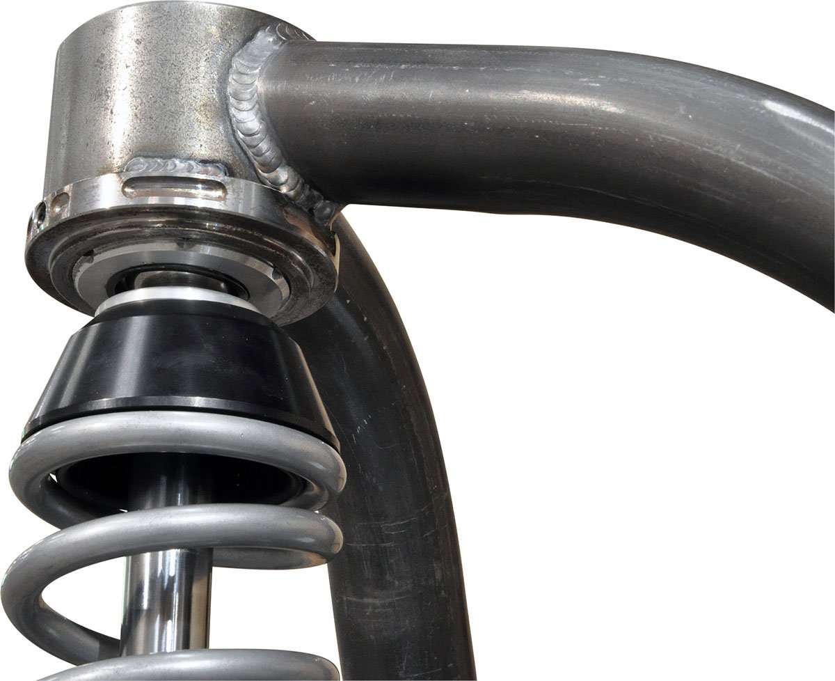
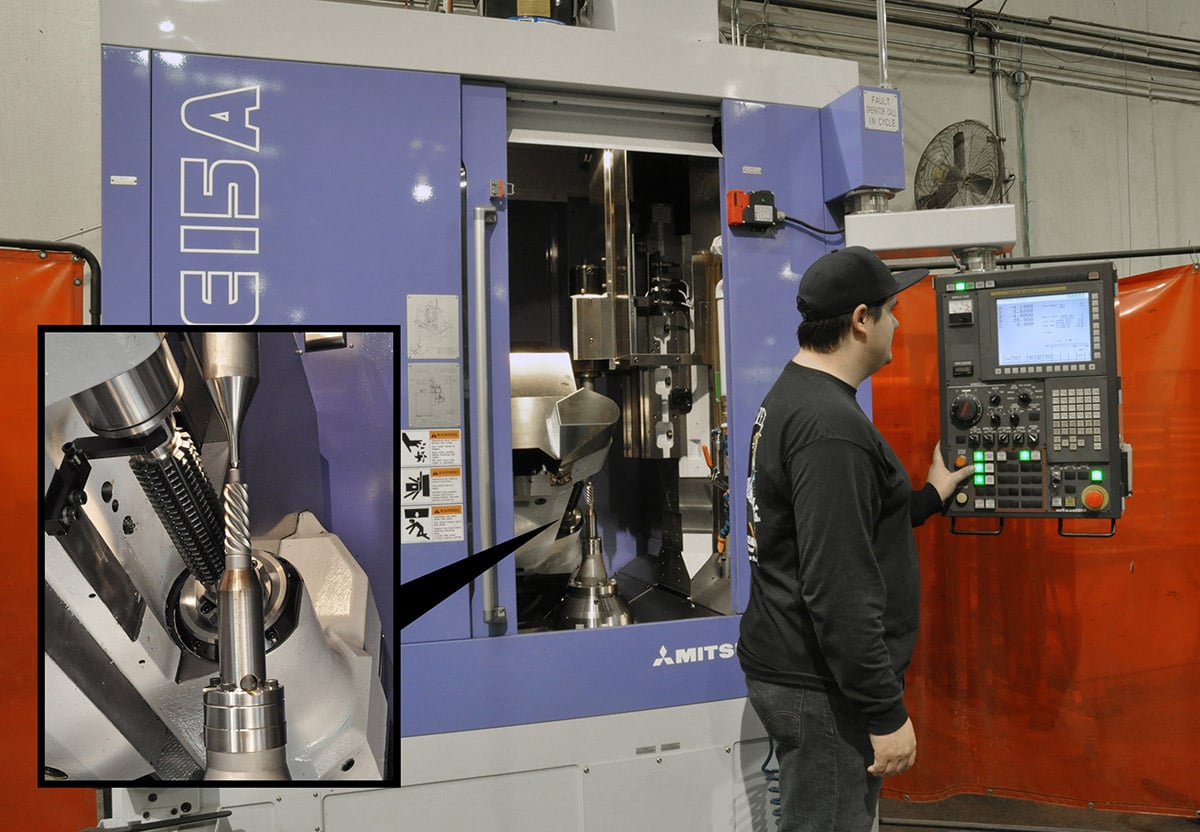
Throughout the entire manufacturing process, the team at Chassisworks paid a great amount of attention to detail in regards to all of the supporting components. One such component was the adjustable-height upper strut mount. This upper mount is comprised of an intricately-machined boss that has been threaded, and then welded onto the frame assembly. To build this and most of their other intricate pieces, Chassisworks uses a Mazak Integrex 5-axis machine. After the boss is welded into the frame, the strut is then threaded into the upper mount. For most applications, the adjustable mount is not necessary, but Chassisworks wanted to provide racers with a mechanism to lower the vehicle that didn’t ultimately change the suspension’s geometry, or the strut’s spring rate.
We followed the manufacturing process from measuring the chassis, to welding plates, bending tube, and assembling the front end.
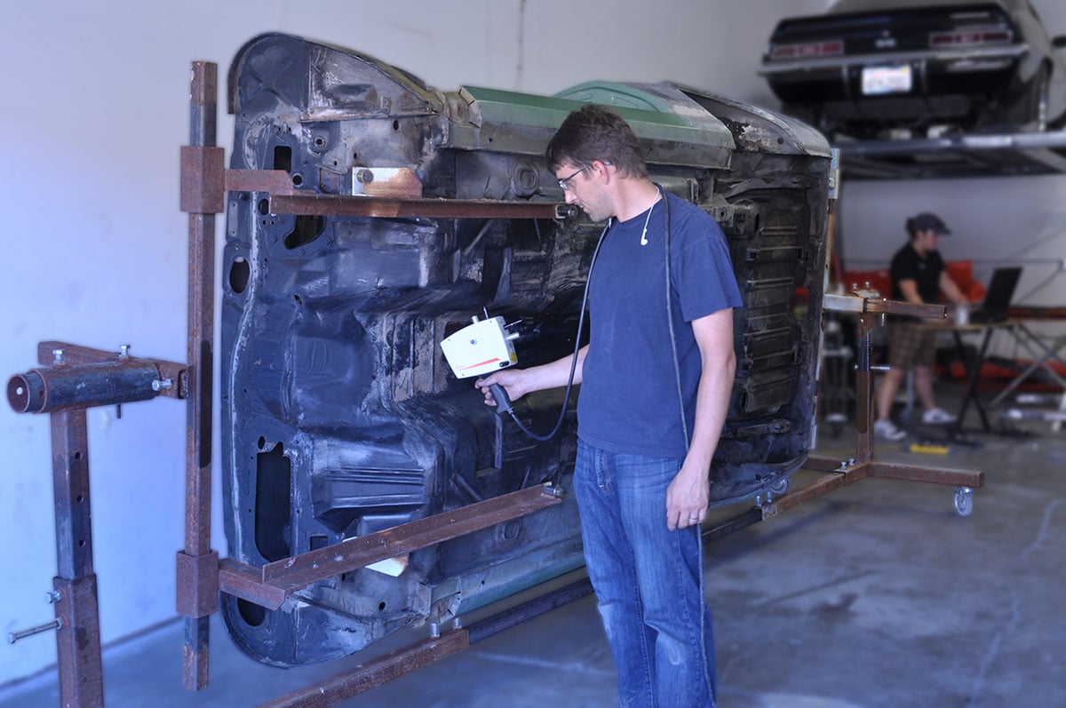
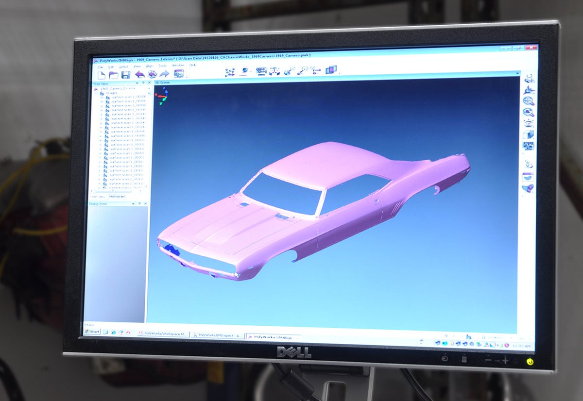
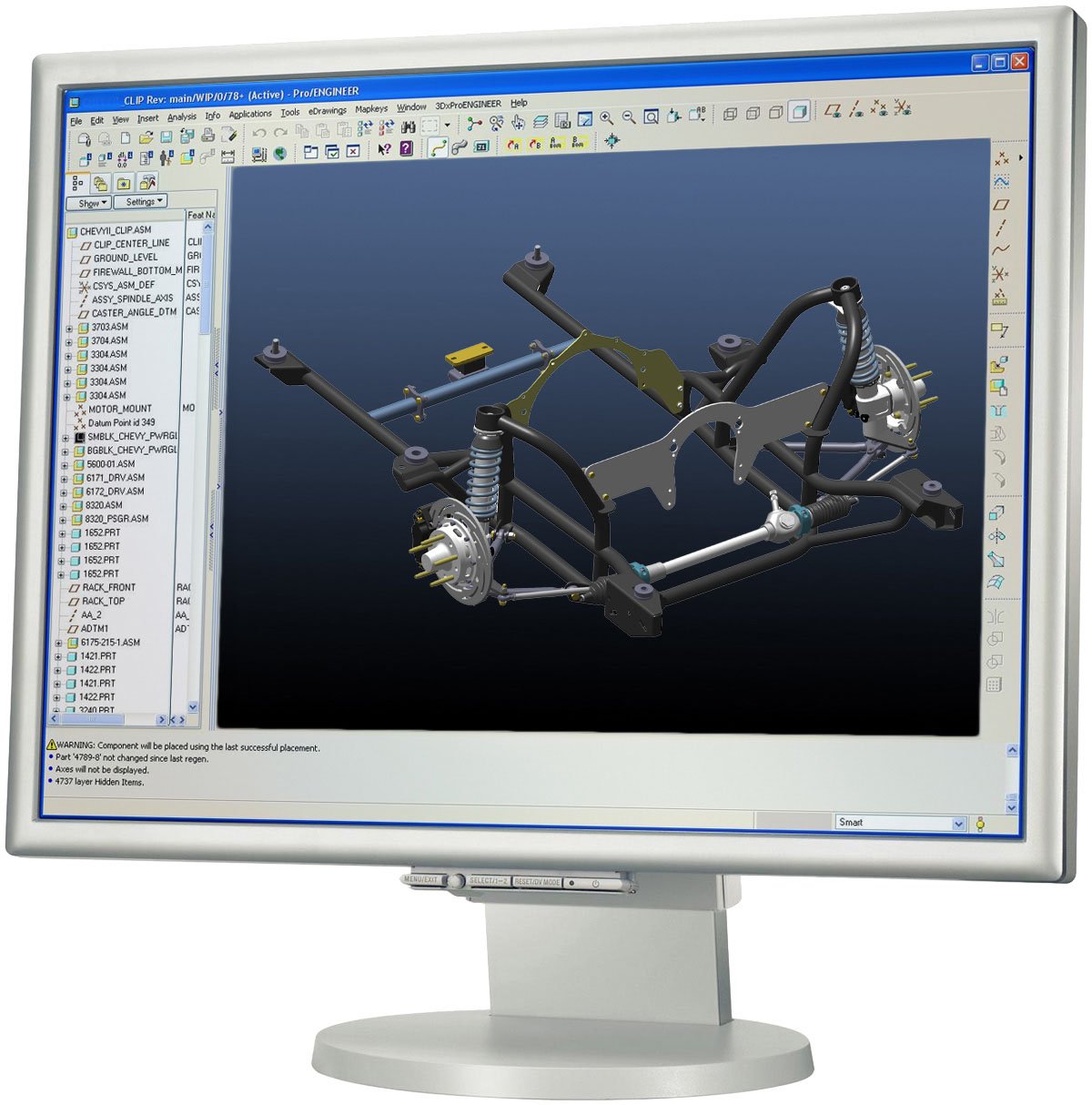
(Left) All surfaces and features of the chassis are scanned. Here, the firewall and forward subframe mounts are being scanned. (Center) A partially completed scan model of the exterior surface. This is later combined with the interior scan to create an accurate digital representation of the vehicle platform. (Right) The 3D vehicle model helps the team move from initial concept to physical prototype and production. The entire clip and suspension are designed, stress analyzed, and checked for clearance in the computer-modeling environment.

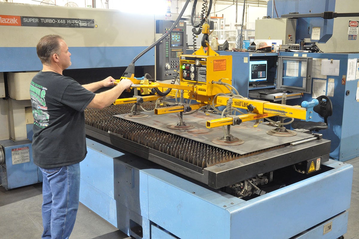
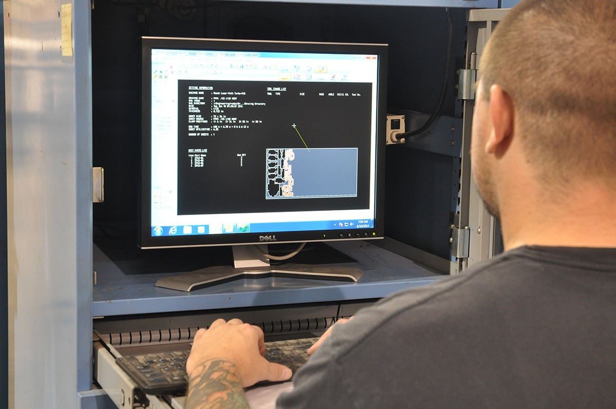
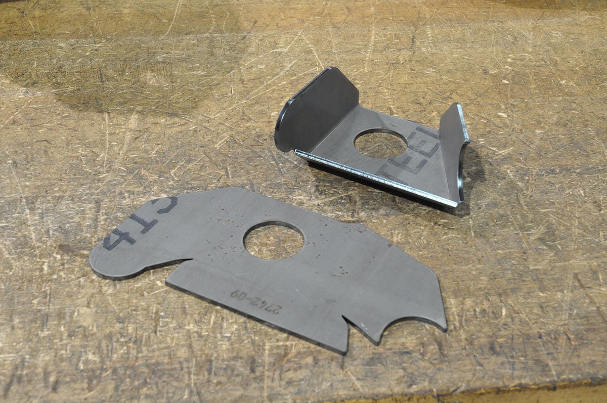
(Left) Nearly all of the mounting brackets found on the strut clip are formed from sheets of laser-cut 4130 material. Here, Chassisworks’ jib crane moves a sheet of material from a pallet stack (out of frame) to the laser bed. (Center) The operator guides the sheet into position and releases the suction used to lift the sheet. (Right) The part numbers and quantity are entered into the control software. The program then organizes the parts orientation to most efficiently use the material. Remnant sheets are recorded in the software, and are recalled when needed for an appropriate work order.
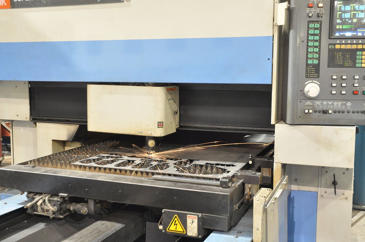
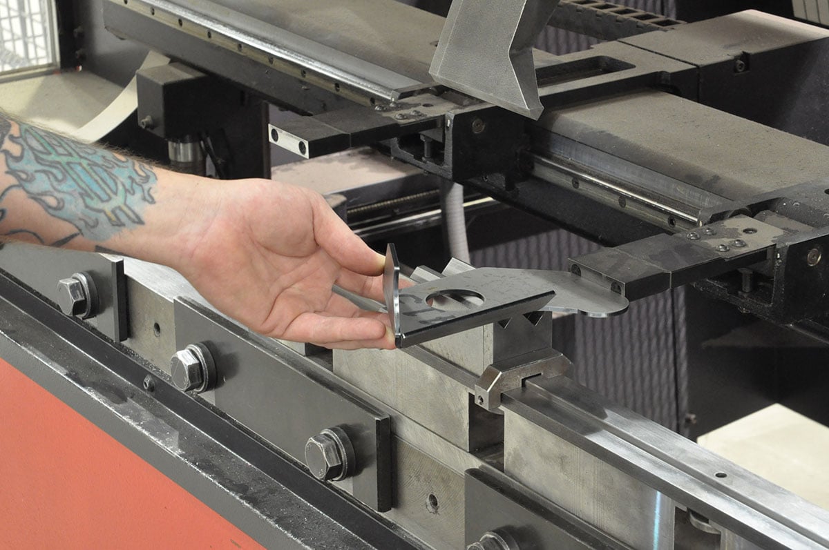
(Left) The laser goes to work by first etching part numbers onto the sheet for individual components before cutting the part. (Center) The lower firewall mounting bracket features separate bends. Prior to each bend, the backstop is robotically-positioned at the required distance before the die moves down to create the bend. (Right) An important part of the bending system is the digital bend measurement gauge. On the first batch, each bend is immediately measured to verify accuracy.
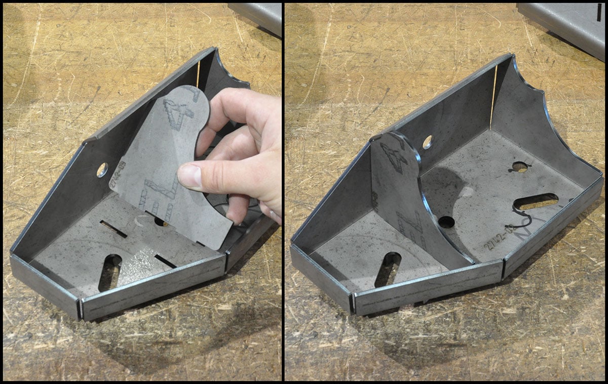
(Left) The digital gauge transmits the measurement back to the machine-control software, and minor corrections in the bend program are made to ensure subsequent parts are within tolerance. Once the program has been fine tuned, the remaining parts can be run with periodic quality checks. Less advanced press brakes are not capable of this level of accuracy, and cannot be calibrated to the strict tolerances required by Chassisworks. (Center) Here is the bracket as it comes off the laser, and after the three bends are formed. (Right) Chassisworks manufactures some of the most intricate sheet metal assemblies in the automotive aftermarket. The effort put into engineering and parts accuracy pays off by eliminating the need for fixtures in some cases, while still guaranteeing finished assembly accuracy. This three-part assembly is one of the optional factory bumper mounts, and is an example of a self-fixturing sub-assembly.

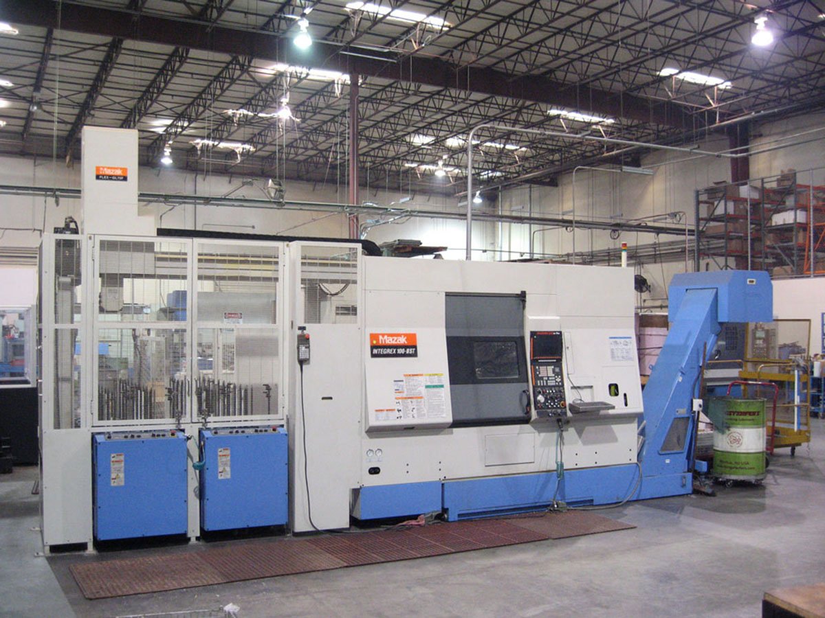
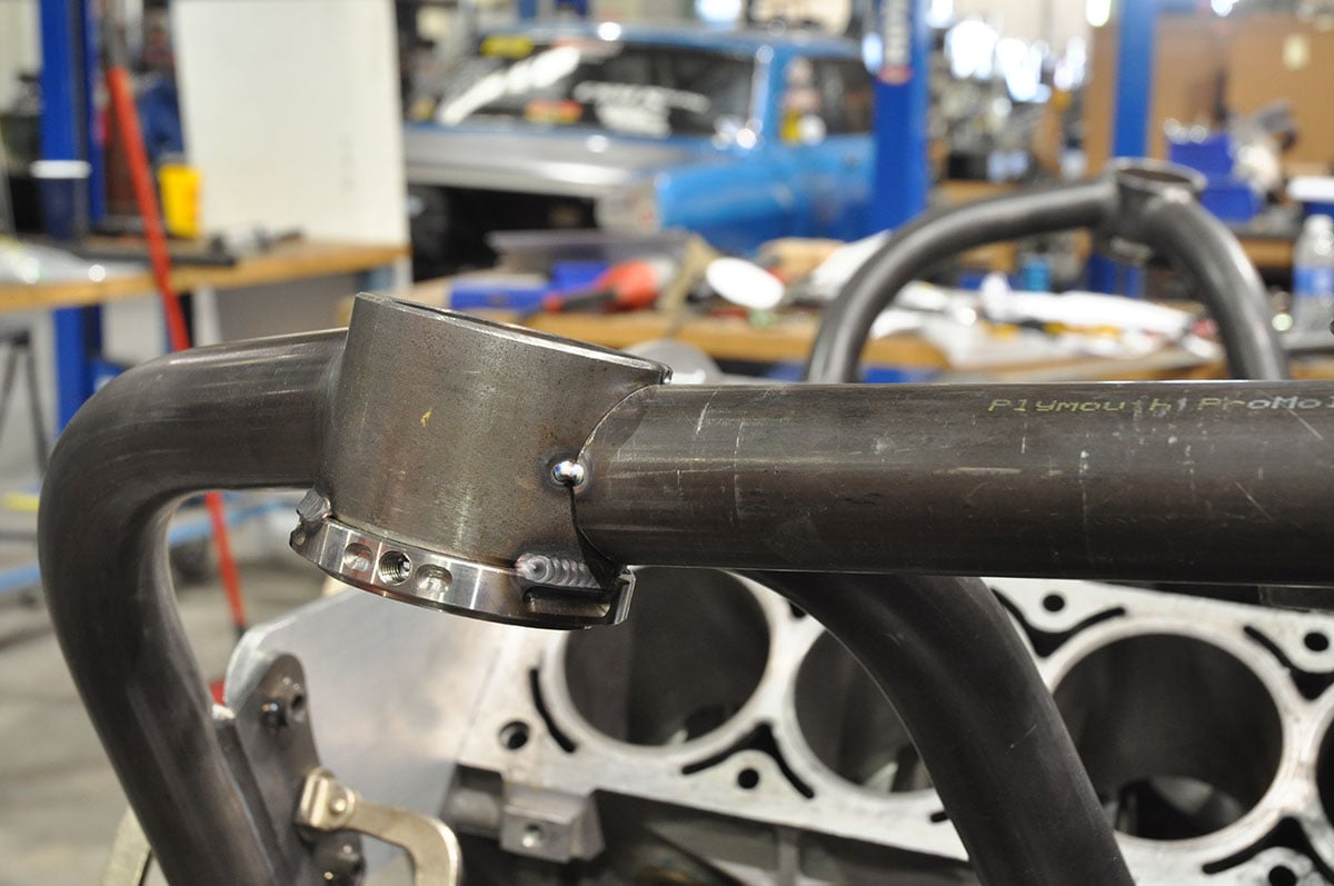
(Left) Here is the bumper mount as it is used on the strut front clip. The clip going on our Camaro will exclude the tube structure since we are using fiberglass and carbon body panels. (Center) One of the built-in clip features is the adjustable-height upper strut mount. The threaded collar welded to the clip is made using Chassisworks’ CNC machines. (Right) The Mazak Integrex is a 5-axis machine that creates many of the intricate smaller parts produced in the factory.
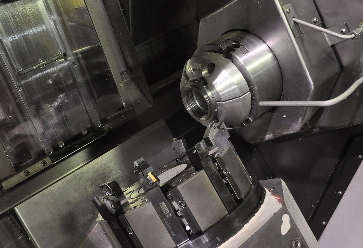
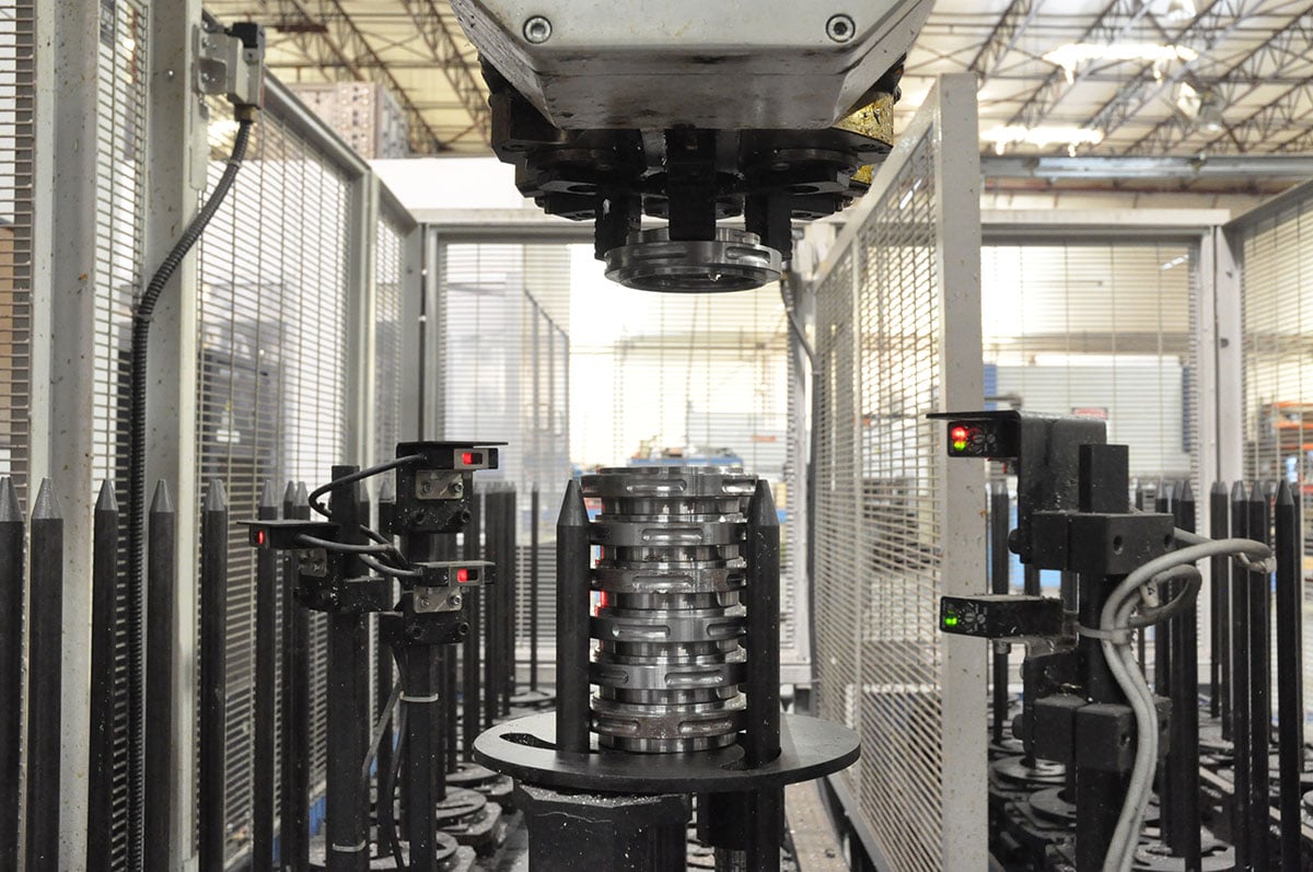

(Left) The automation of the Integrex machine is rather impressive. A blank is picked up by robotic arm and loaded into the turret jaws. Machine work is performed on one side of the part before passing the part to an opposing turret to finish the remaining side. (Center) Completed parts are stacked by the robotic arm in one of the receiving towers. Empty towers are shown at the left and right. When running high-volume parts like the coil-over spring seats, each of these towers will be full to run hundreds of parts without interaction from the operator. (Right) Shown are a pair of finished adjuster bosses ready for welding onto the strut clip.

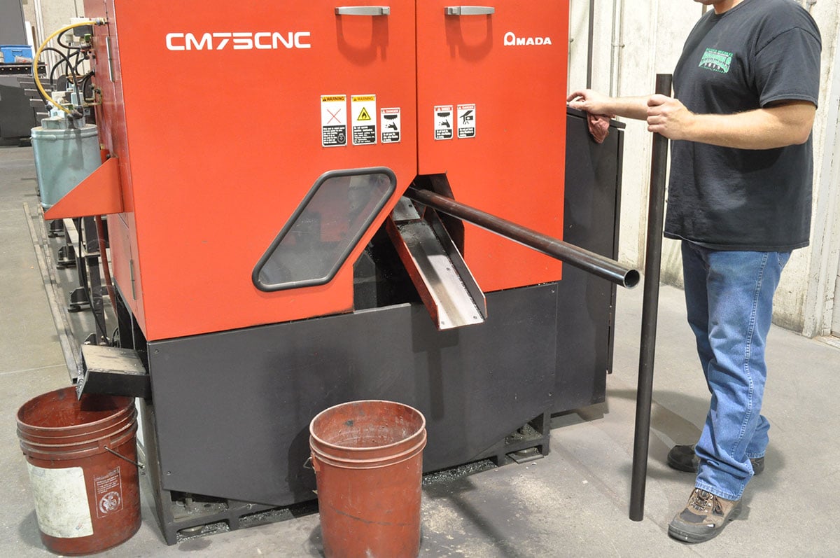

(Left) Sections of the front clips made from 4130 tubing start life at Chassisworks’ CNC high-speed saw. Twenty-foot lengths of material are loaded into the saw hopper ahead of programming. The automated hopper loads a tube into position and feeds the tube into the cutting area. (Center) An operator waits at the output end of the machine to grab the cut tubes that are now ready for the bender. (Right) The operator loads the tube that the bender shifts into the correct position. The bender then performs the bend, rotating the tube and then making the next bend. Shown here is Chassisworks' smallest bender, which makes anything from exhaust header primaries to round-tube chassis'.
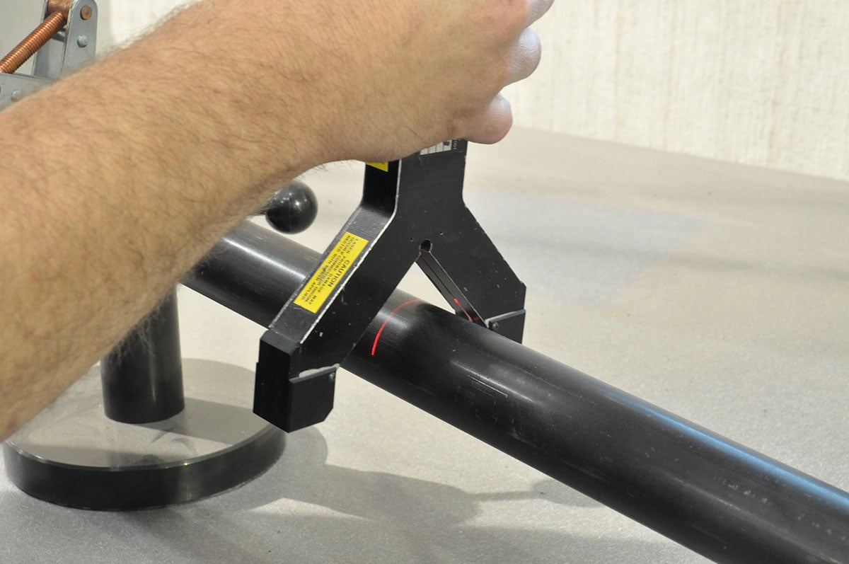
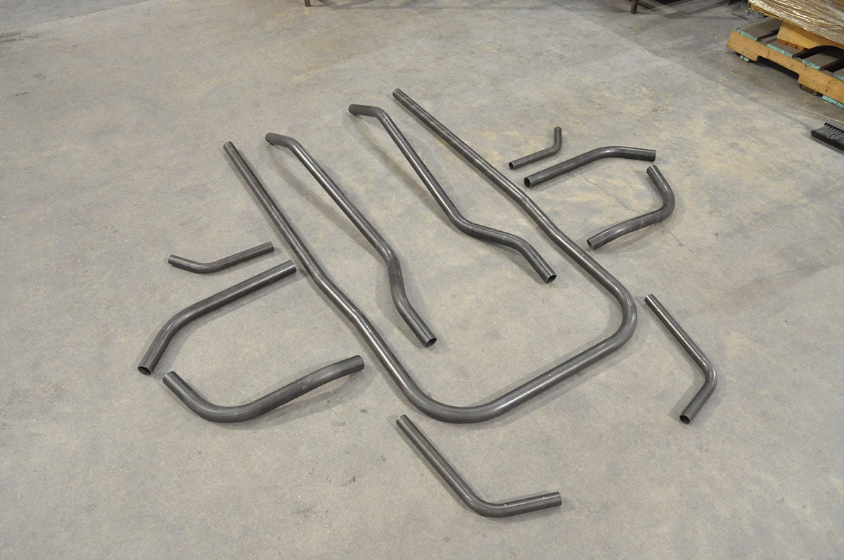
(Left) The first run of tubes is laser scanned for accuracy, and the new coordinates are fed back to the bender controller. The revised bend program is saved to run parts with a higher degree of accuracy. (Center) In this image, the laser that casted onto the tube is visible. The scan arm does not come into contact with the tube. (Right) These are the completed tubes ready for final fitting into the weld fixture.
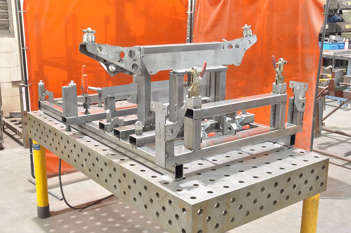
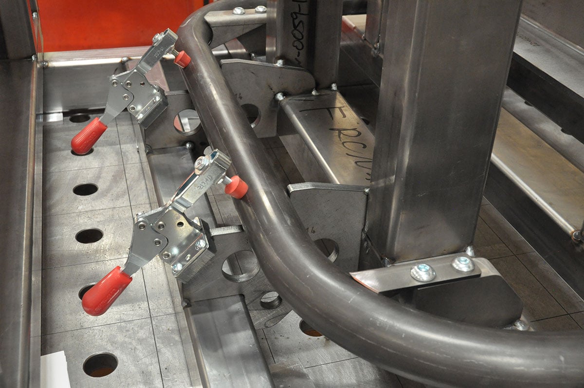
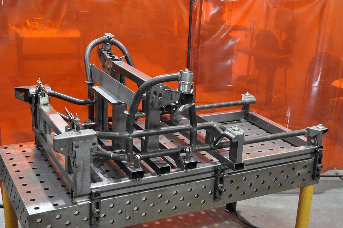
(Left) The weld fixture is designed during the 3D modeling stage of development and is built using its own set of manufacturing prints. (Center) Each tube is trimmed or notched by a weld technician, and clamped into the fixture. Brackets (like the rack mounting brackets shown here), are located and held in place with hardware. (Right) With all components locked into place, the assembly is tacked and welded in a specific order to avoid warping before being allowed to cool. Small areas that are unreachable in this process are completed once the clip is removed from the fixture.
Shown is a completely welded assembly that is ready for shipping. The transmission cross-member and upper firewall support struts are attached during final installation on the vehicle.
The front end is made to work with Chassisworks’ steering components. While many shops are comfortable building A-arms and miscellaneous components, not many are comfortable with harder components like steering racks. In the case of Chassisworks, they developed and manufacture the steering rack in-house.
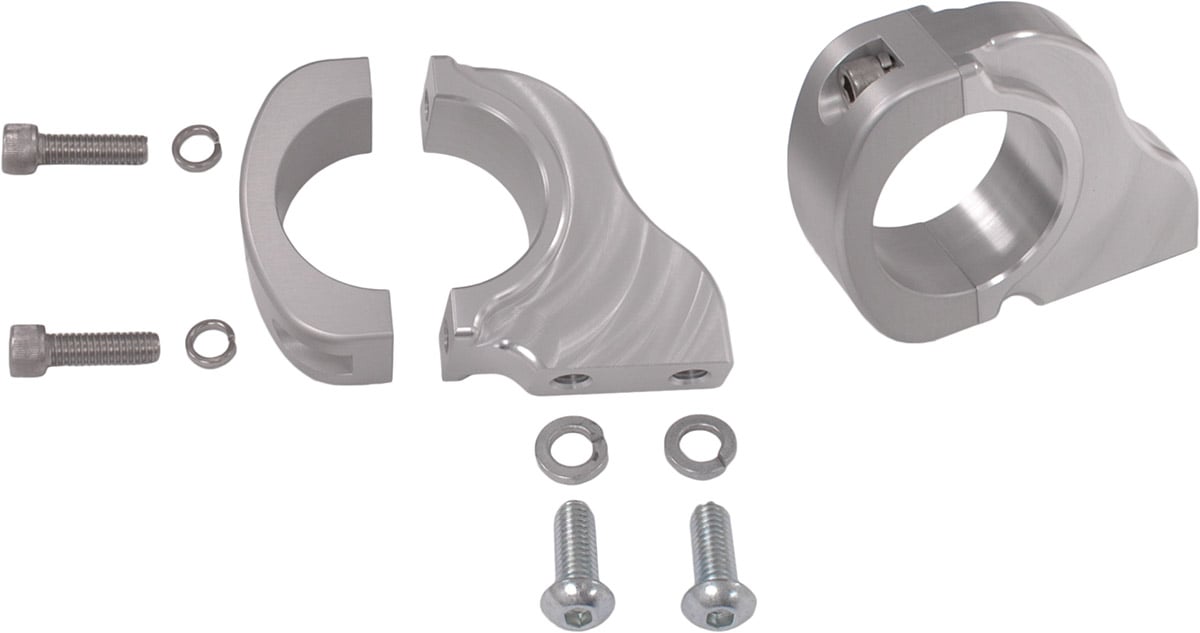
The steering rack gears and shaft (left) that enable 6-5/8 inch of travel, is made in-house, along with the billet housing and clamps (right).
“Unlike most shops, we use our own racks with our own gears made in house. A specialized device called a hobbling machine is required to build the gears. Most shops farm this work out due to costs.” Alston Sr. noted.
The steering rack-housing, gears, and column are all designed and manufactured by Chassisworks. As a result, each component is designed to work together, and is a direct bolt in for the Camaro.
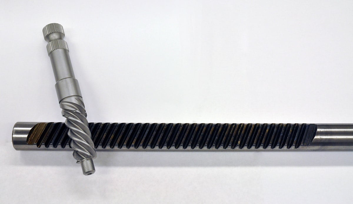
The steering rack gears and shaft (left) that enable 6-5/8 inch of travel. The cost of R&D and equipment like a hobbling machine (right) can be prohibitive to many companies in this industry.
Did Someone Say Struts?
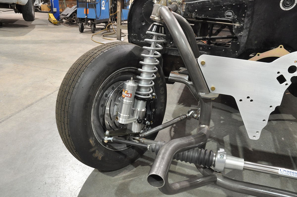
One of the most prominent features of the Chassisworks’ first-gen Camaro package is the integrated strut conversion. The conversion starts with a 100-percent custom strut that features a completely integrated spindle, brake mount, steering arm, lower A-arm mount, and a billet strut body. Chassisworks was able to add a fully integrated strut, while keeping the build in-house. This is done by utilizing VariShock, which also happens to be a Chassisworks company. Having a strut manufacturing facility on hand made building the proper strut an easy task.
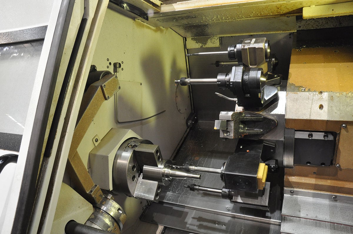
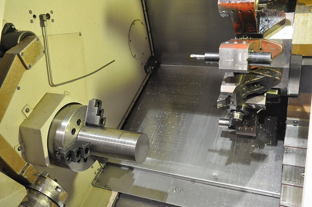

(Left) Beginning with a blank cut from bar stock, the side that will eventually house the adjustment knobs is faced and beveled. The remaining backside features are completed on a different machine (Center) Multiple cutting tools create the axle stub and detail features. This particular machine operates as a traditional lathe by rotating the blank and moving a series of cutting tools along the material to carve out the axle stub and spindle nut threads. (Right) Secondary turrets add horizontal mill functionality and allow machining of the threaded caliper mounting holes, spindle washer groove, and cotter pin hole.
VariShock manufactures numerous struts and shocks, our package came with a high-rebound force, drag-specific strut, a piggyback reservoir body, and dual-adjustable mounts. VariShock had an existing line of drag-race oriented struts, but this strut, has been re-engineered for radial and outlaw-style drag racing applications.
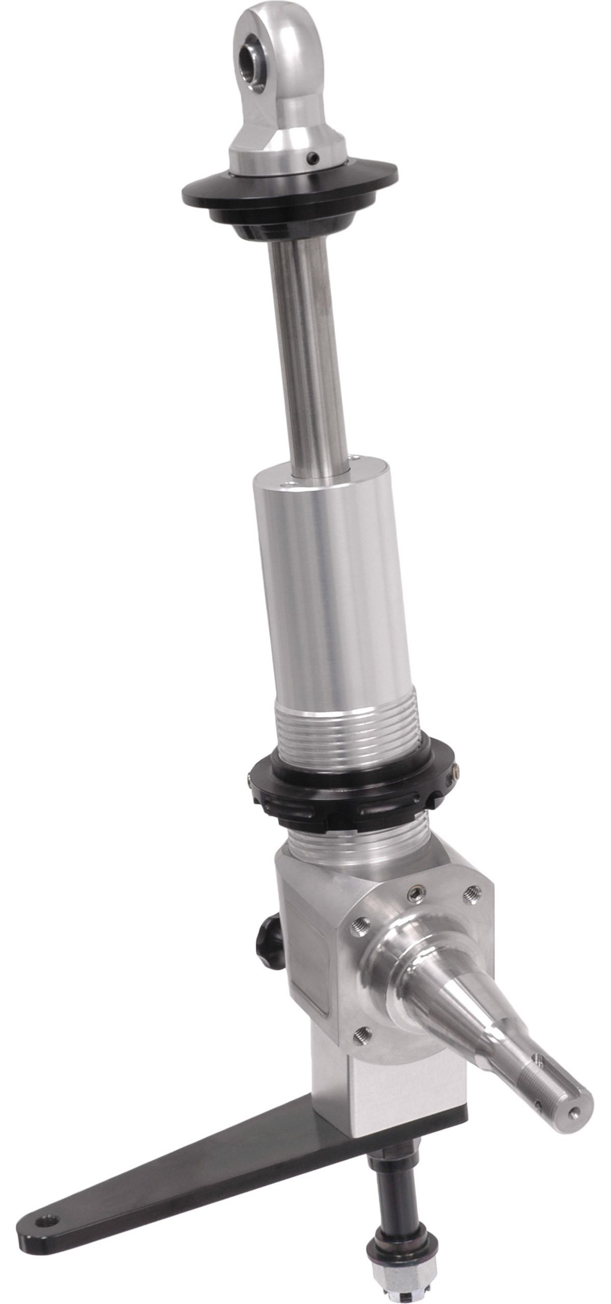

(Left) VariShocks billet strut as constructed with spindle mount and steering arm. (Right) The fully loaded strut package being used for this build complete with piggyback reservoir, coil spring, and brakes. The strut and brake assembly can be installed as a complete unit.
Chassisworks promised to give us the full scoop behind the strut manufacturing processes in a coming feature, but we were able to talk them into giving us a sneak peek.
Installation
Once the front end is fully assembled, it is placed in a crate for transport with the supporting components. Also shipped with the assembly, components and hardware, is a fully detailed 28-page installation guide, complete with pictures.
With the instruction manual, installation is very straightforward, but requires patience–and at some times, an extra set of hands. The guys at Chassisworks took us step by step through a typical installation.

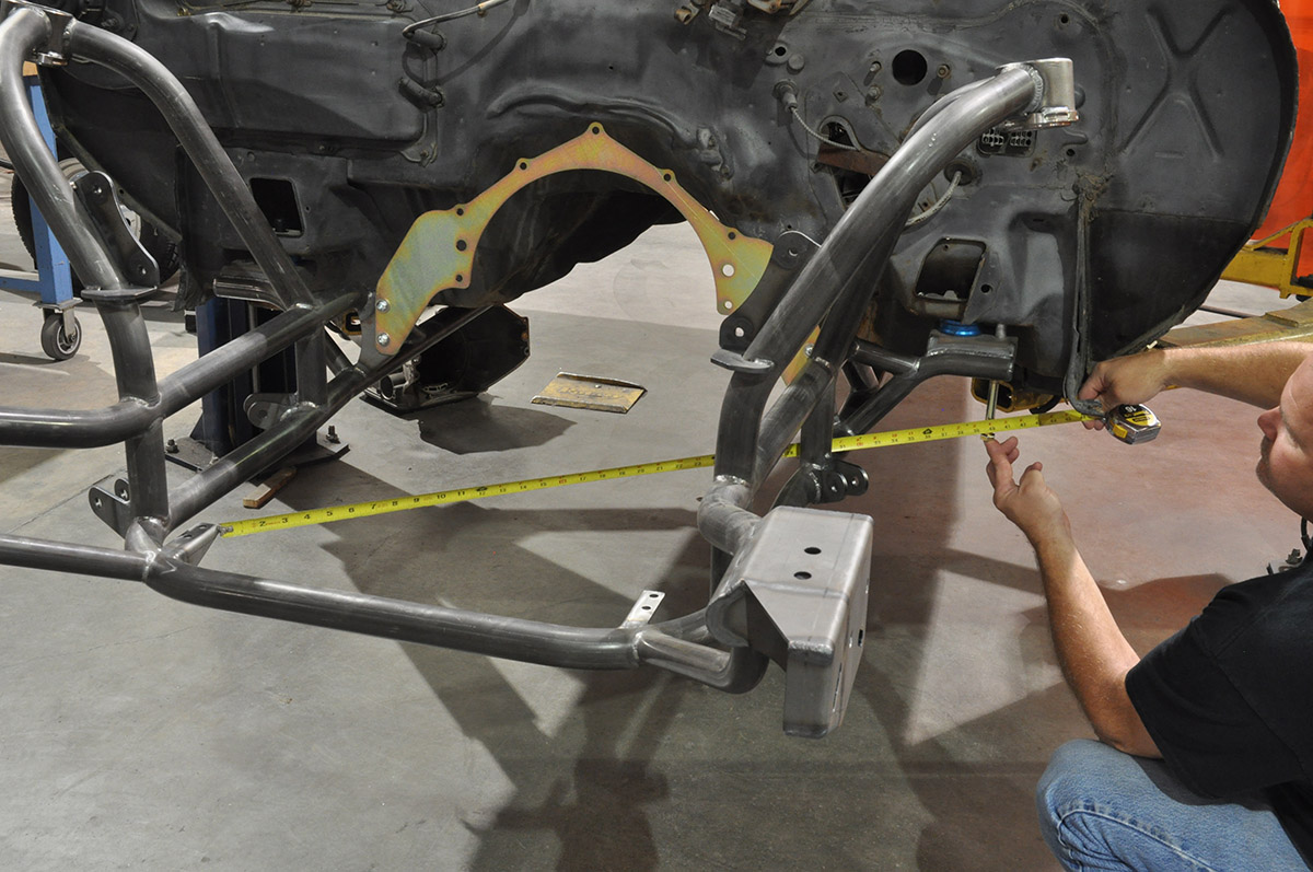
(Left) Before raising the clip into position, the factory mounting-boss threads are chased. (Center) The clip can now be raised into position while the bolts are loosely installed to hold it. (Right) Diagonal measurements taken from the rack mounts to the opposing alignment pin are compared to verify that the clip is square to the chassis.
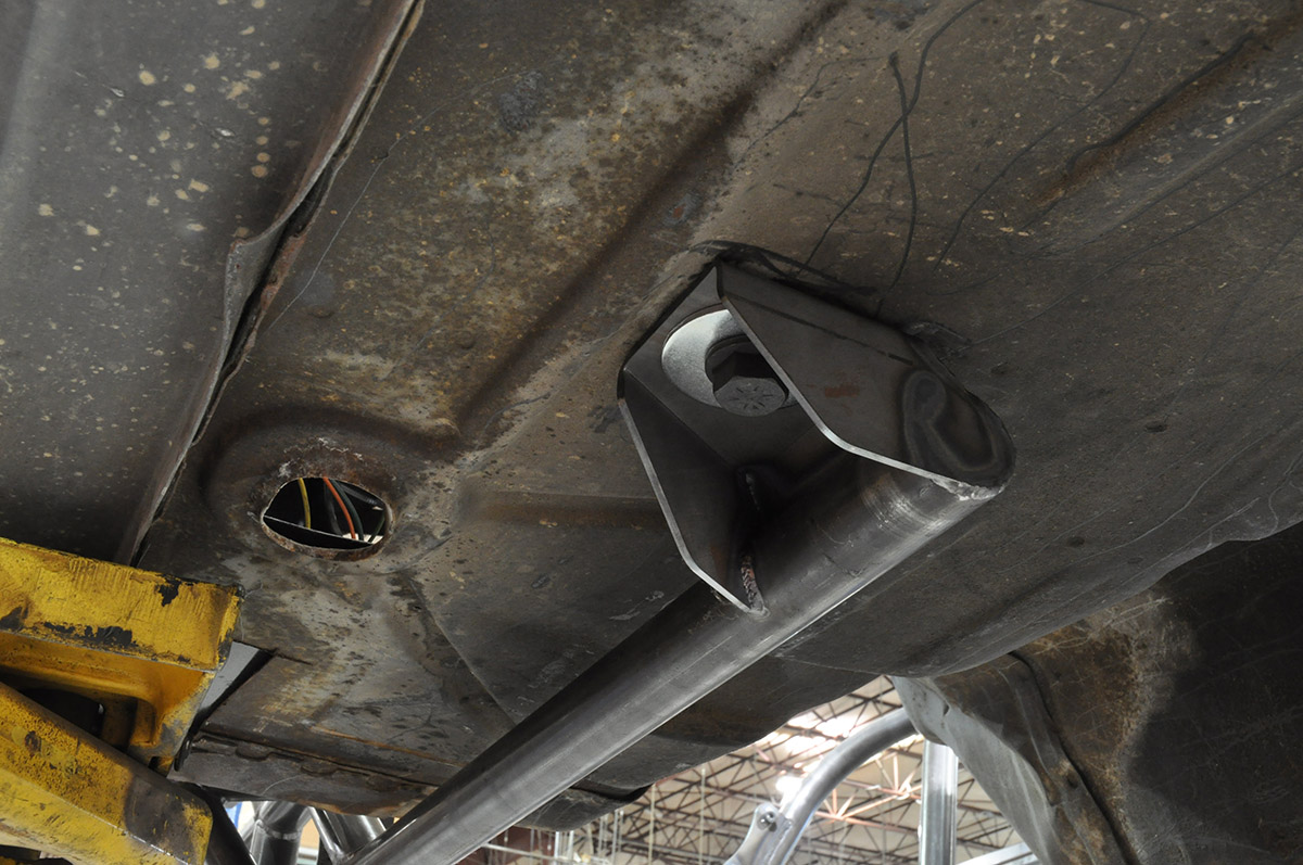
(Left) The body bushings are removed to lower the vehicle stance, and the mounting bolts are tightened. (Center) The rear end of the frame rail bolts directly to the rear factory mounting location. Here you can see that the body bushings are left out. (Right) With the clip securely hung from the chassis the upper support struts are installed and used to connect the top strut mount directly to the cage side.
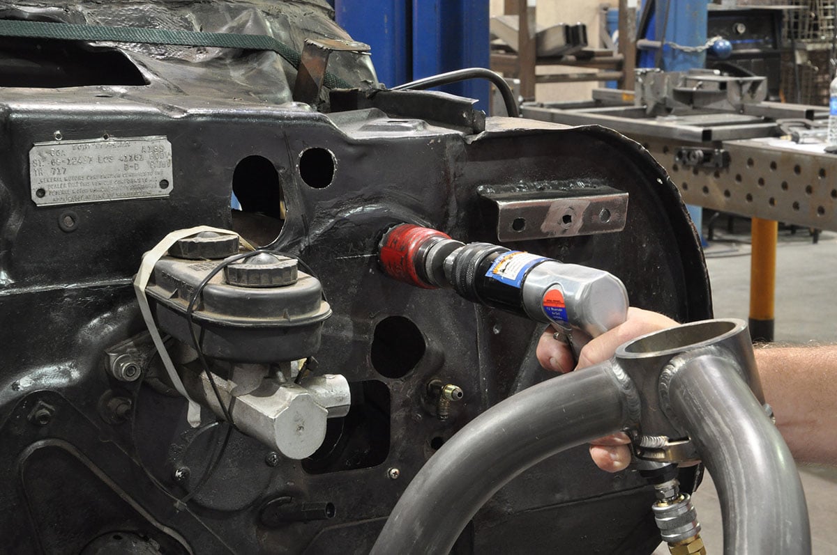

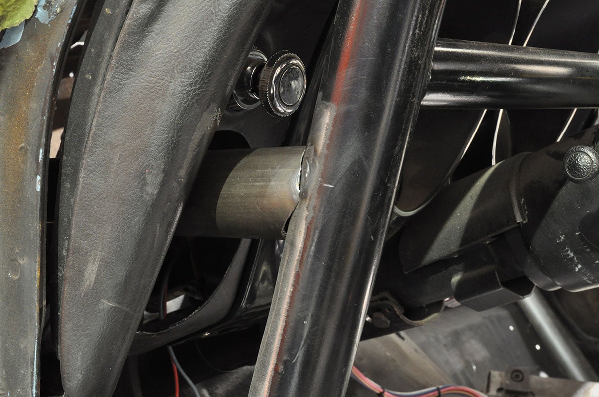
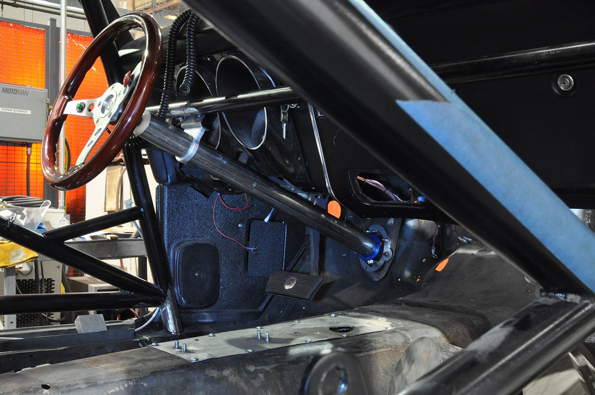
(Left) A 1-3/4-inch hole is drilled through the firewall just inboard of a reinforced area on the interior. A length of welding rod was used prior to drilling to estimate the correct location and angle to meet the cage side. (Center) A mounting flange is welded to the firewall. This flange will facilitate the bolt in installation of the forward strut bars. In typical roll cage installations, this bar is welded to the A-pillar bar. (Right) The tube meets the cage side just above the height of the steering column.
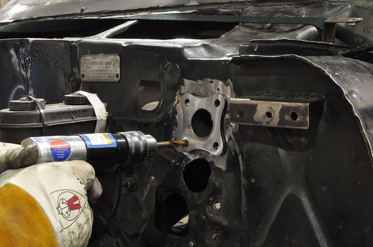

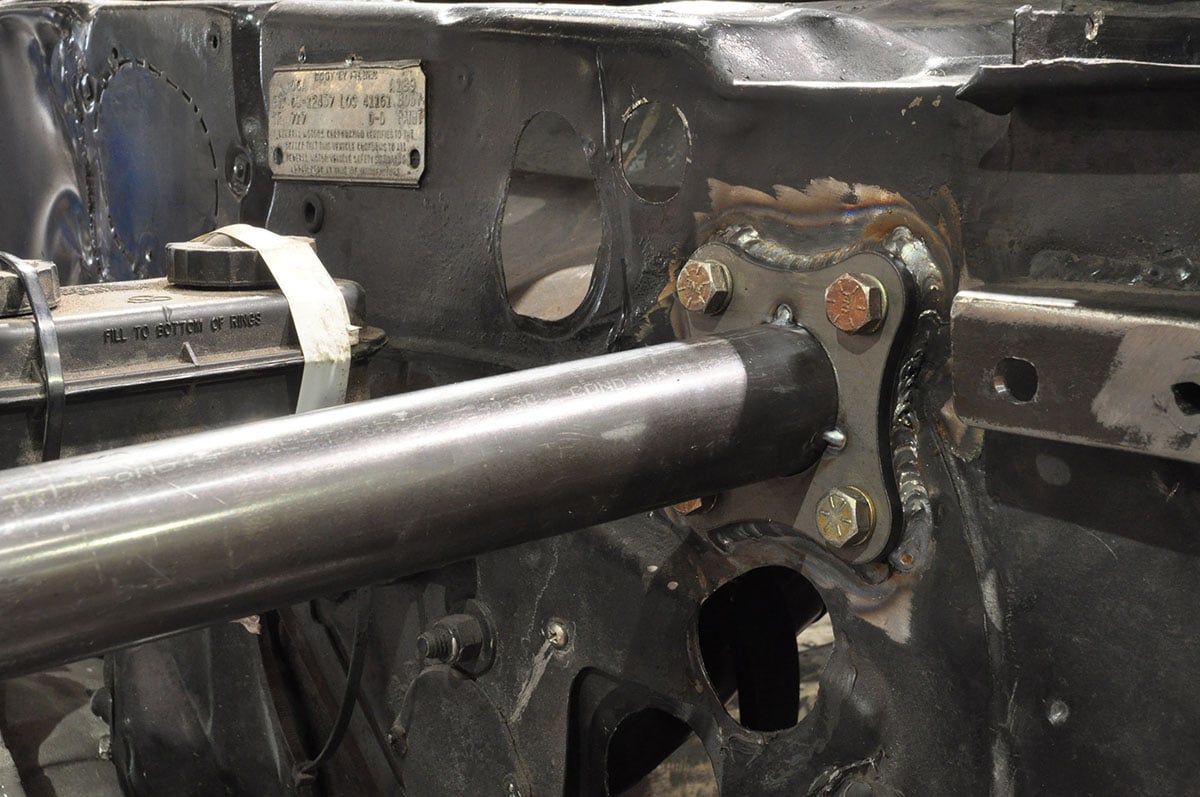
(Left) Holes are drilled through the firewall, and the bolts are installed before welding the plate and cage-side joint. (Center) The bolts are used to hold the plate tight against the firewall while welding completely around the plate. (Right) The front half of the strut tube is fitted with an identical flange plate before bolting it in place. It is then tacked and welded while bolted to the firewall.
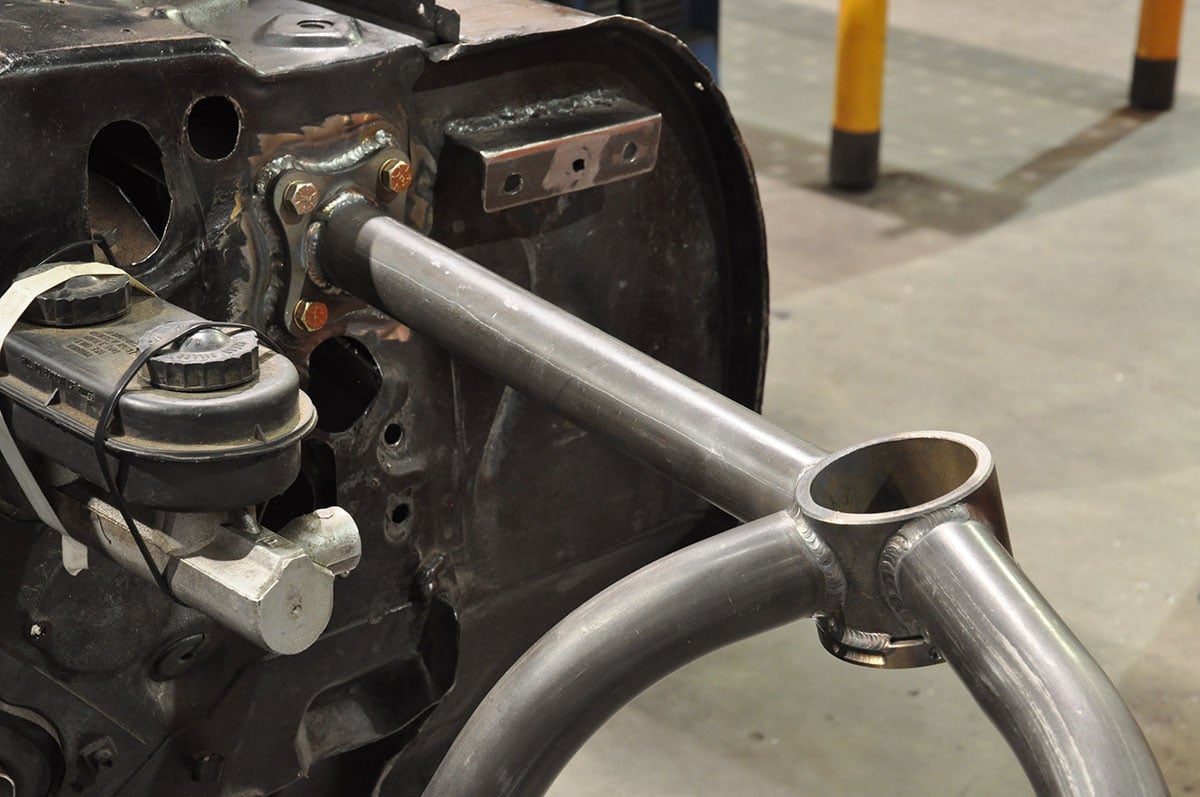
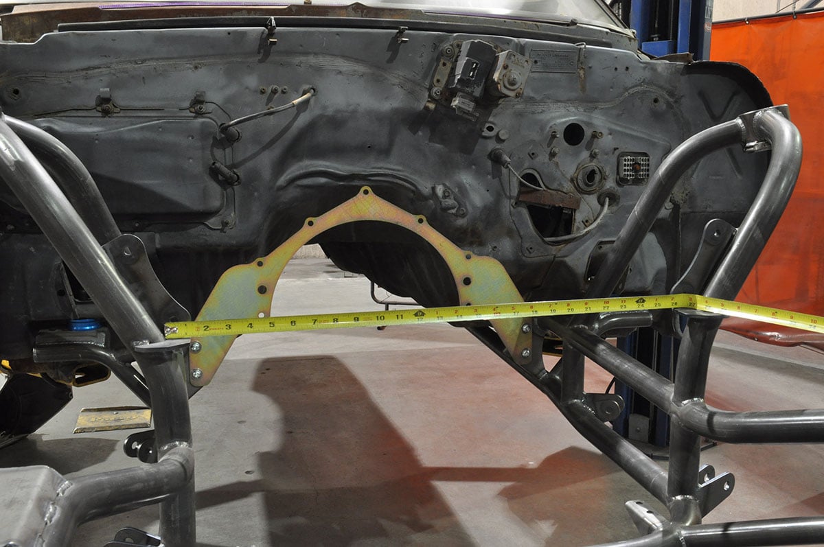
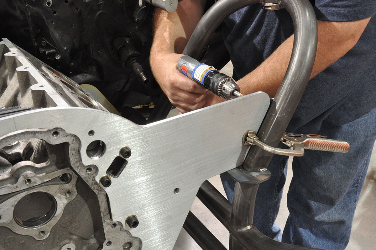
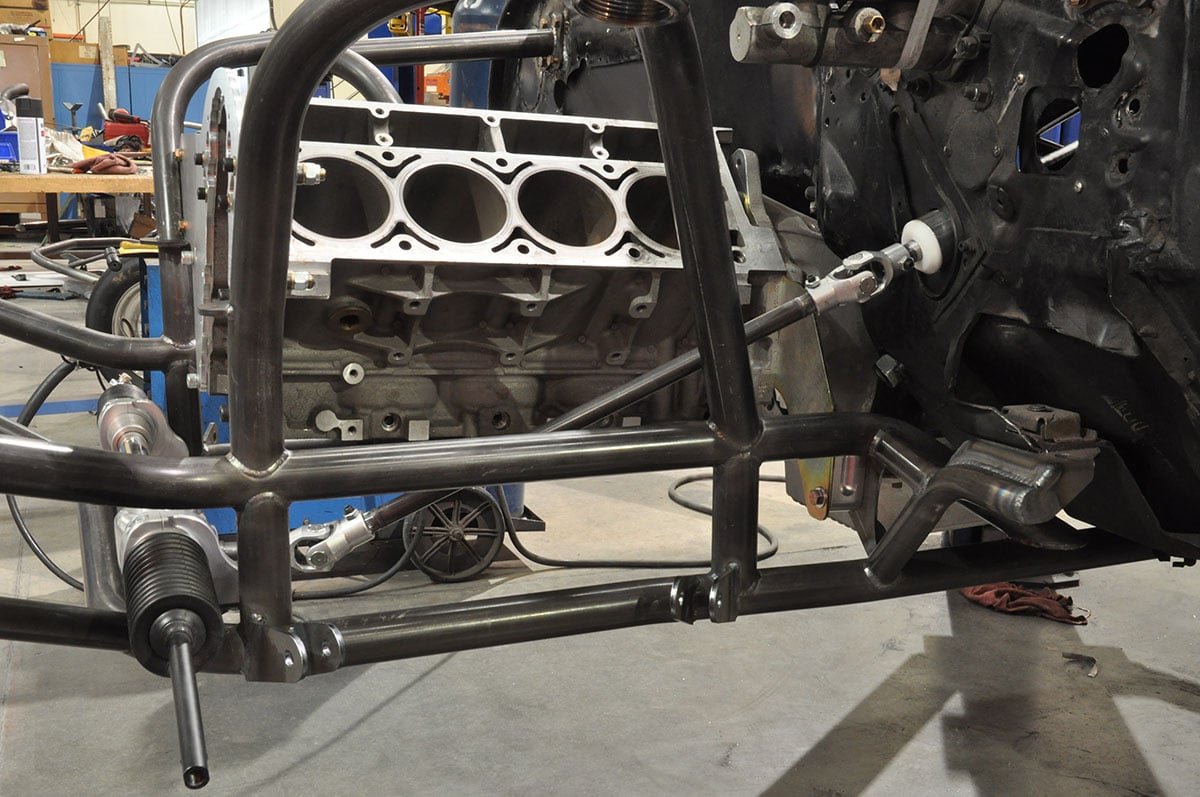
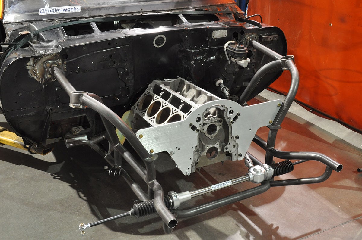
(Left) The front end of the strut tube attaches to the upper suspension strut mount. (Center) During final installation, tubes are welded along the frame rails to connect the rear frame and roll cage to meet NHRA chassis certification specs. (Right) The first step of drivetrain installation is bolting the mid-plate into place, and then measuring for the motor plate at the top and bottom of the brackets.
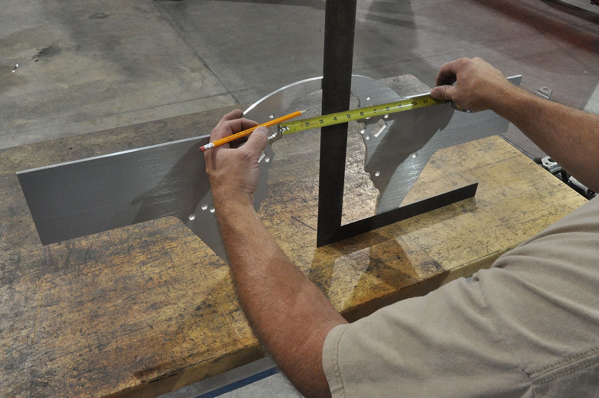


(Left) The motor plate is trimmed to fit between the upright tubes of the clip. Using the water passage holes, we mark the centerline of the motor plate. (Center) From the centerline the distance between the top and bottom of the clip mounting brackets are marked. (Right) A cut line is drawn with a radius added at each corner for cosmetic purposes.
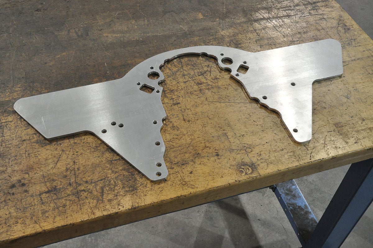

(Left) After the cuts have been made and edges sanded smooth, we are ready to move forward. (Center) The engine block is bolted to the mid- and motor-plate to make sure the plate is not flexed or bowed when drilling the mounting holes. (Right) The complete mock-up drivetrain is now mounted in the car in preparation for fitting the transmission crossmember.
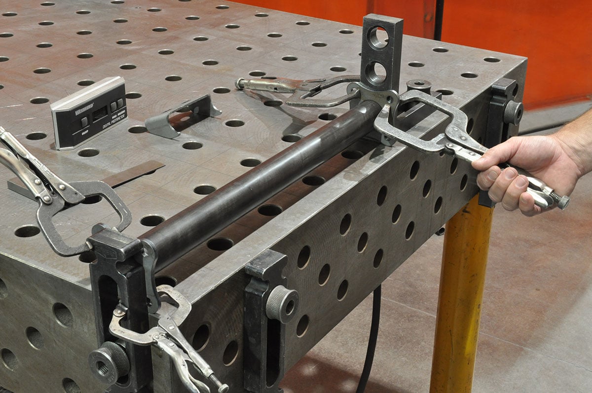
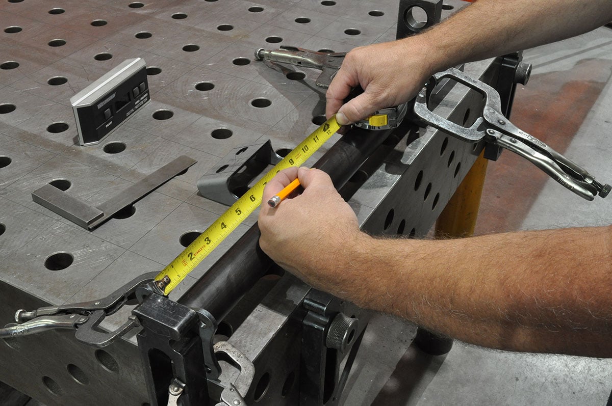
(Left) The distance between the frame rails is measured, and a piece of 4130 tubing is cut to length. (Center) The tube is cut into three lengths; the long center span is the removable crossmember and two short lengths that are welded to the frame rails. The center tube is fixtured on the table with a mounting flange squared at each end, then tacked together. (Right) The centerline of the crossmember is marked for the transmission mount bracket.
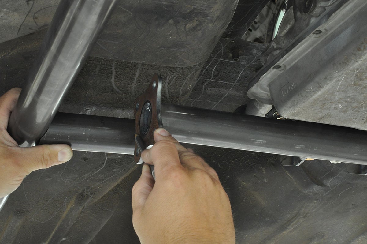

(Left) The drivetrain angle runs at a 3-1/2 degree downhill slope. That angle should be verified by measuring the angle along the bottom or back of the engine block before welding the mount bracket. (Center) To give us one less thing to hold on to, the removable crossmember was bolted to the transmission to more easily mark a cut line on the shorter end tubes. The cross-member sits slightly higher than the frame rails, requiring the tubes to be cut at an angle. (Right) Before tack welding the outer flanges and tubes, we verify that the crossmember is level.
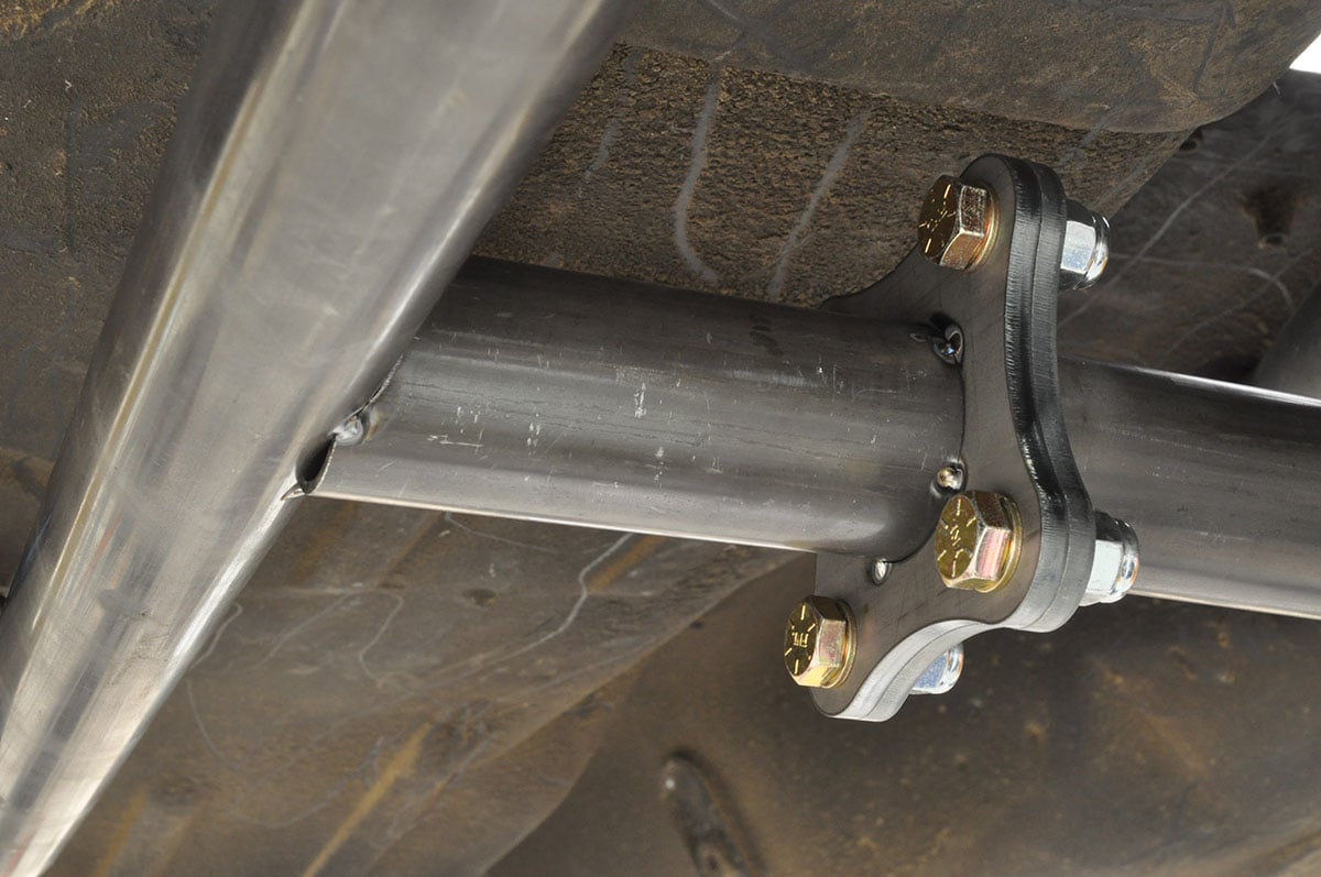

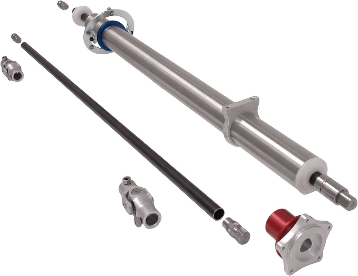
(Left) With the parts securely tacked in, we can continue welding around each joint. (Center) The finished transmission crossmember. (Right) A Chassisworks stainless steel drag-race steering column replaces the factory unit. The 4130 shafts and stainless column tube must be cut to length.


(Left) The spline tube adapters are TIG welded to the steering shaft. (Center) Welds are filed smooth so they do not interfere with the polymer bushings at each end of the shaft. (Right) The column mounts with the supplied billet clamp. A Chassisworks quick-release steering hub has different bolt patterns to fit popular wheels.

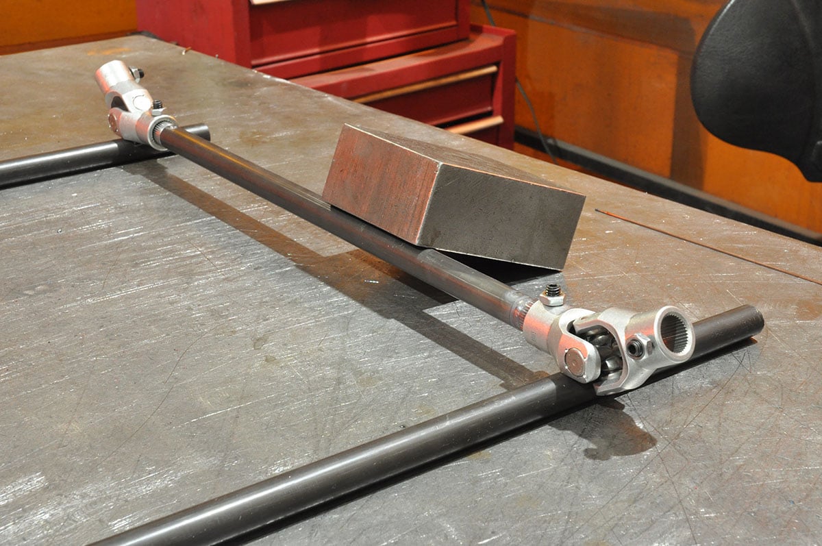
(Left) The pivoting floor mount that is also included in the kit holds the lower column end securely. (Center) We fit the intermediate steering shaft that’s initially mocked up to determine the correct length to cut the shaft. (Right) After cutting the shaft, both U-joints are placed onto the splined tube adapters, and then inserted in the tube. The U-joints are resting on extra lengths of tubing to ensure they are clocked correctly in relation to each other while tacked.
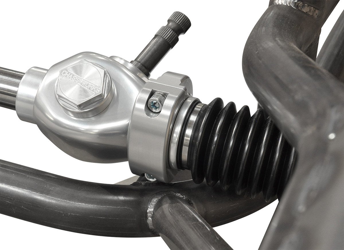
(Left) The completed steering shaft assembly. (Center) The rack mounts allow tilting of the pinion shaft. A welcomed feature when it comes time to make the headers. (Right) The completely mounted rack is ready to attach to the suspension.
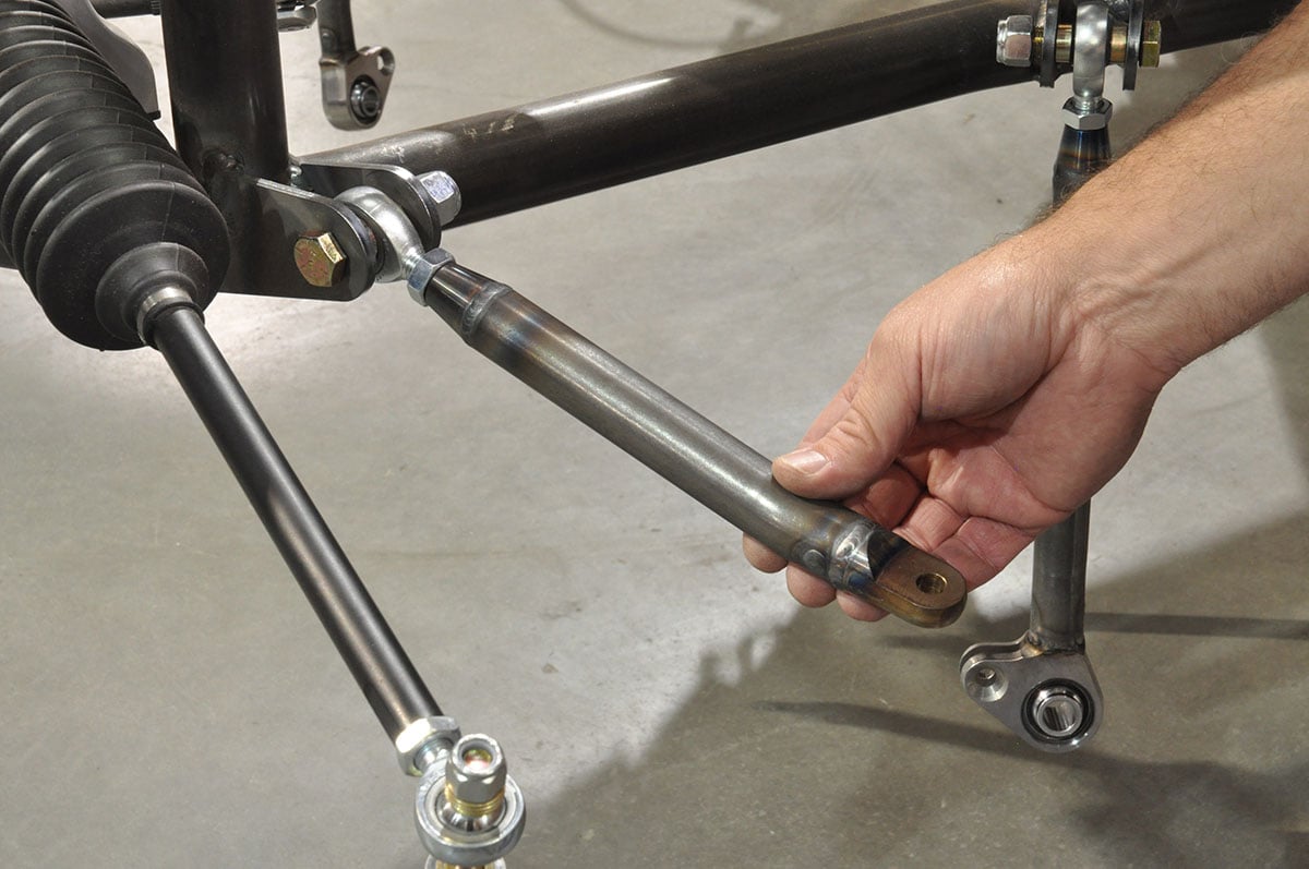
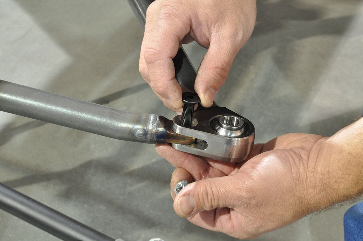

(Left) The 4130-steel lower control arms come factory welded and ready for installation. (Center) The rear link features a billet clevis with spherical bearing. With the lower arm assembled, the strut can be prepared for installation. (Right) Once the brakes are bolted to the strut, the top mounting hardware is assembled.
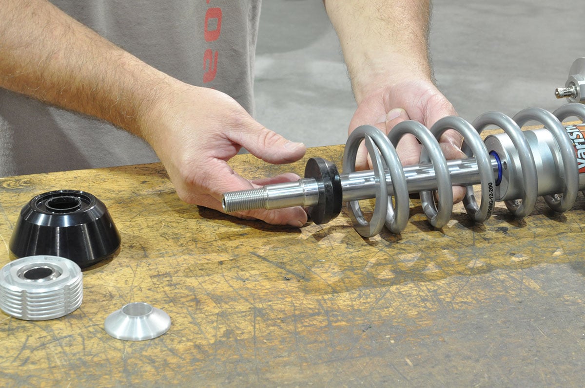

(Left) A tapered bump stop is placed over the piston shaft, followed by the upper spring seat and tapered spacer. (Center) The stem of the piston shaft will sit inside the spherical bearing adjuster. (Right) The piston shaft is held with an Allen wrench as the lock nut is tightened.
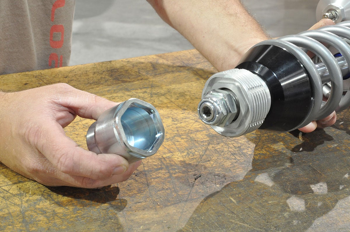
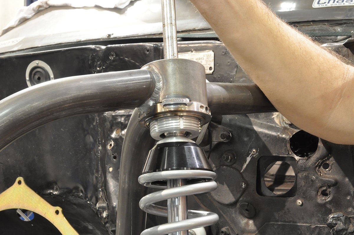
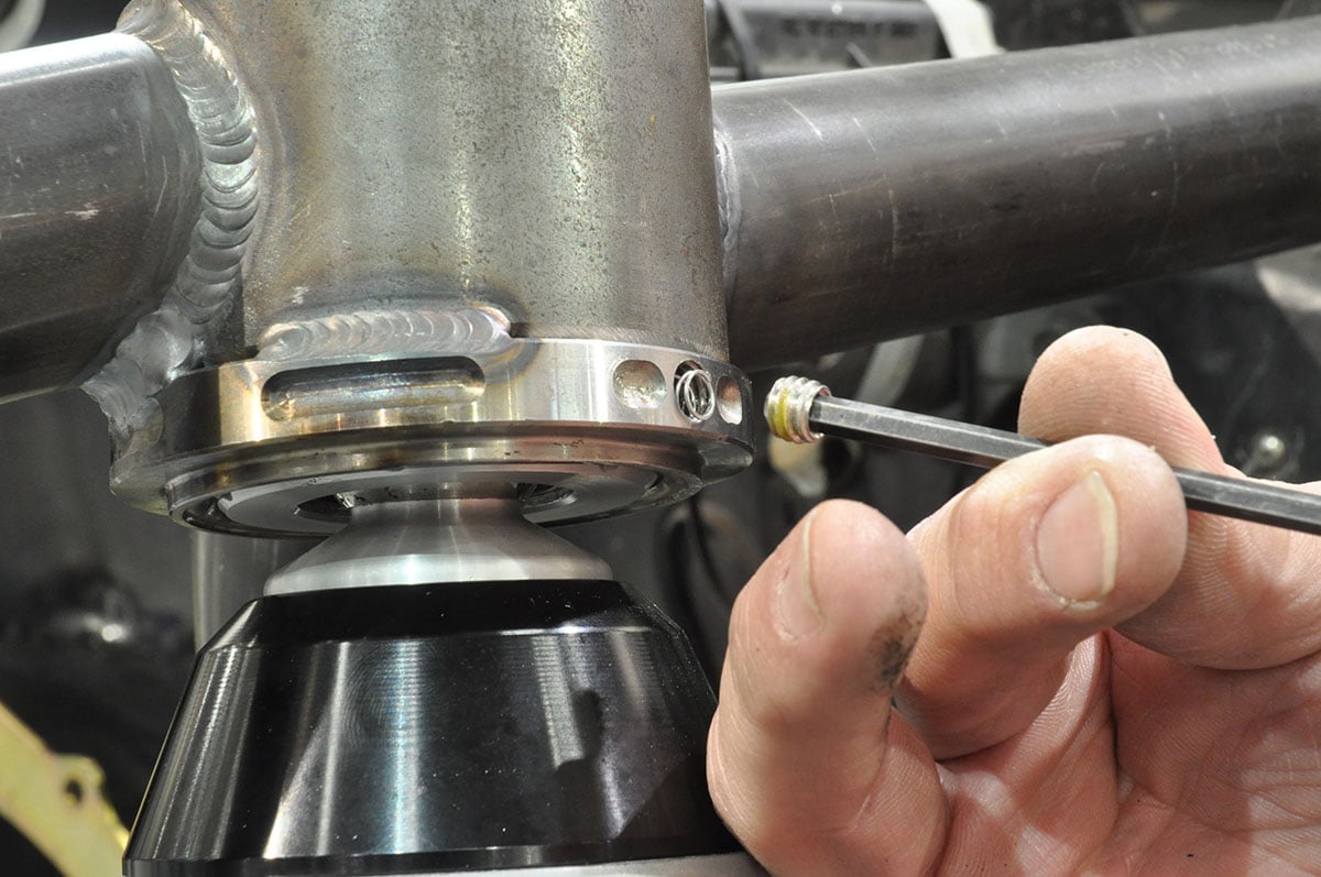
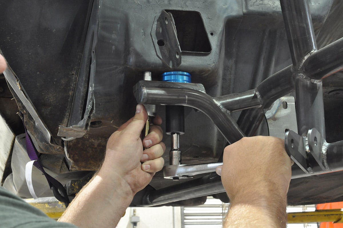
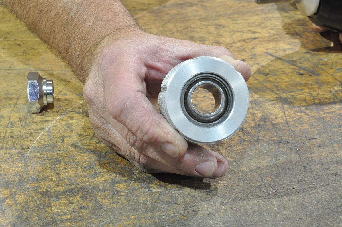
(Left) A Chassisworks designed 1/2-inch-drive socket fits into the rounded hex groove in the top of the adjuster, and is used to raise or lower the vehicle. (Center) Once the threads are started, the hex socket and ratchet are used to draw the strut up into the mounting cup. (Right) The upper mount-collar uses a spring-loaded ball bearing and detents in the adjuster to lock the ride height adjustment.
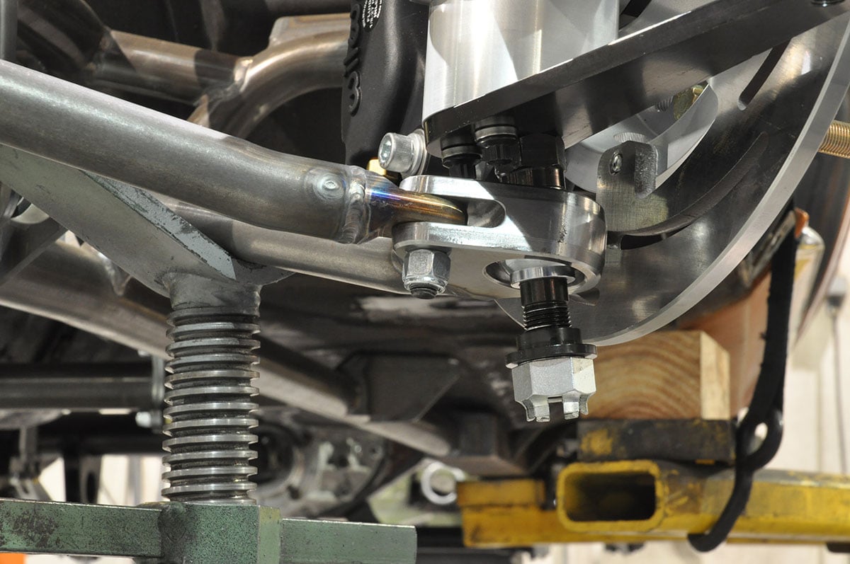
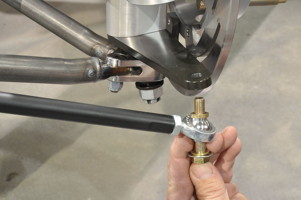
(Left) The bottom strut stem is inserted through the lower control arm bearing, and secured with a Castle nut. (Center) The tie rods also use a spherical bearings, and are attached to the steering arm with Grade-8 bolts . (Right) The driver’s side high-rebound double-adjustable strut with lower control arms, tie rods, and brakes assembled.
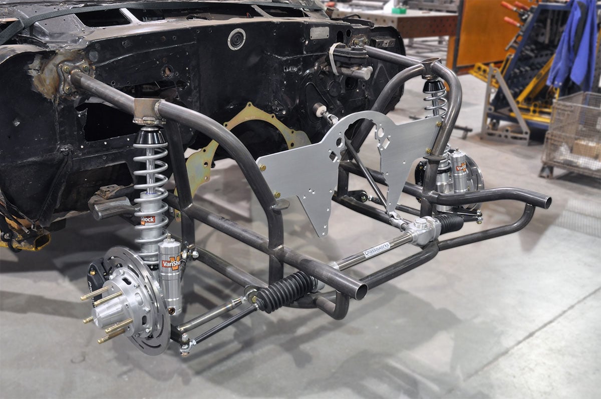
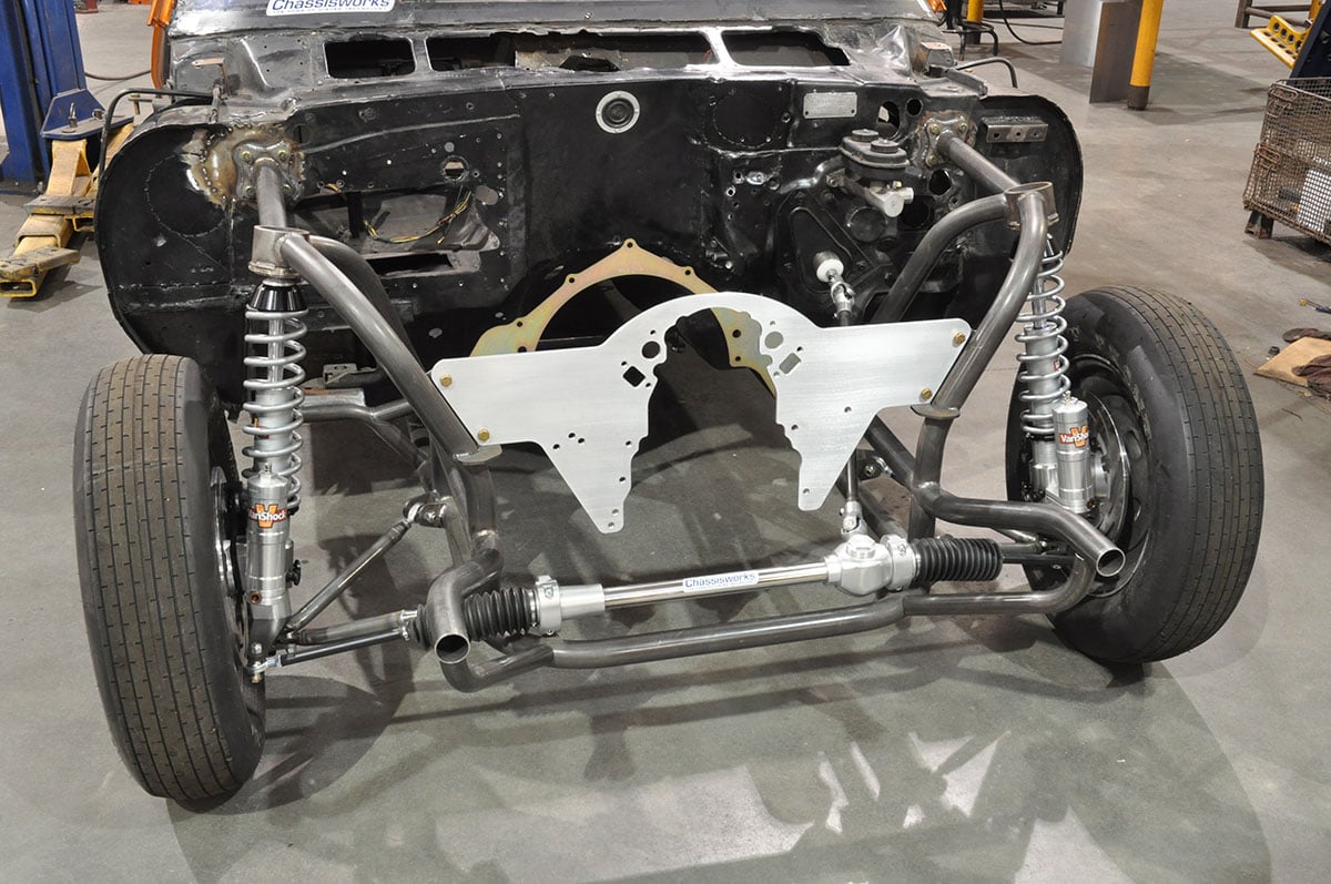
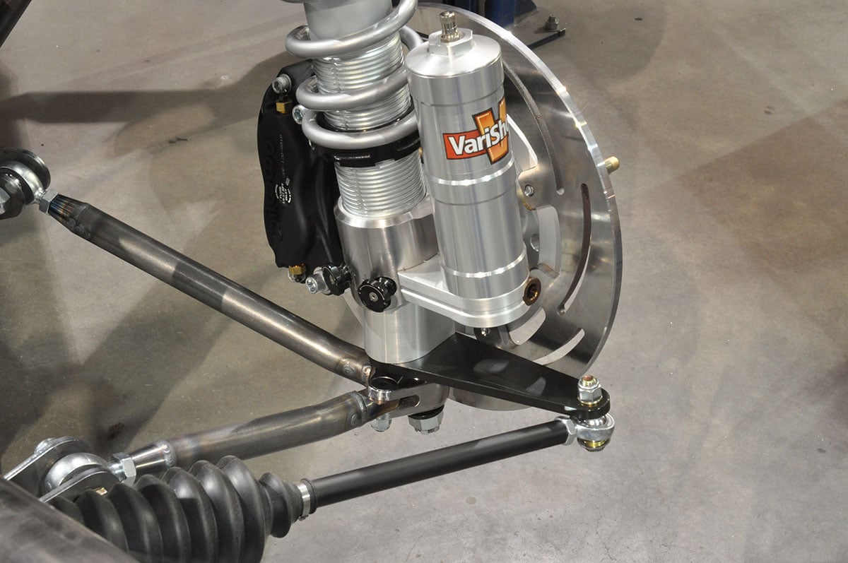
(Left) Chassisworks manufactures almost every component shown here. They are one of few drag-race manufacturers that can produce a nearly 100-percent complete front end in-house. (Center) The front end uses Chassisworks’ reservoir struts from Varishock along with lightweight A-arms and spindles. (Right) The installation once completed with front end, struts, steering and motor plates.
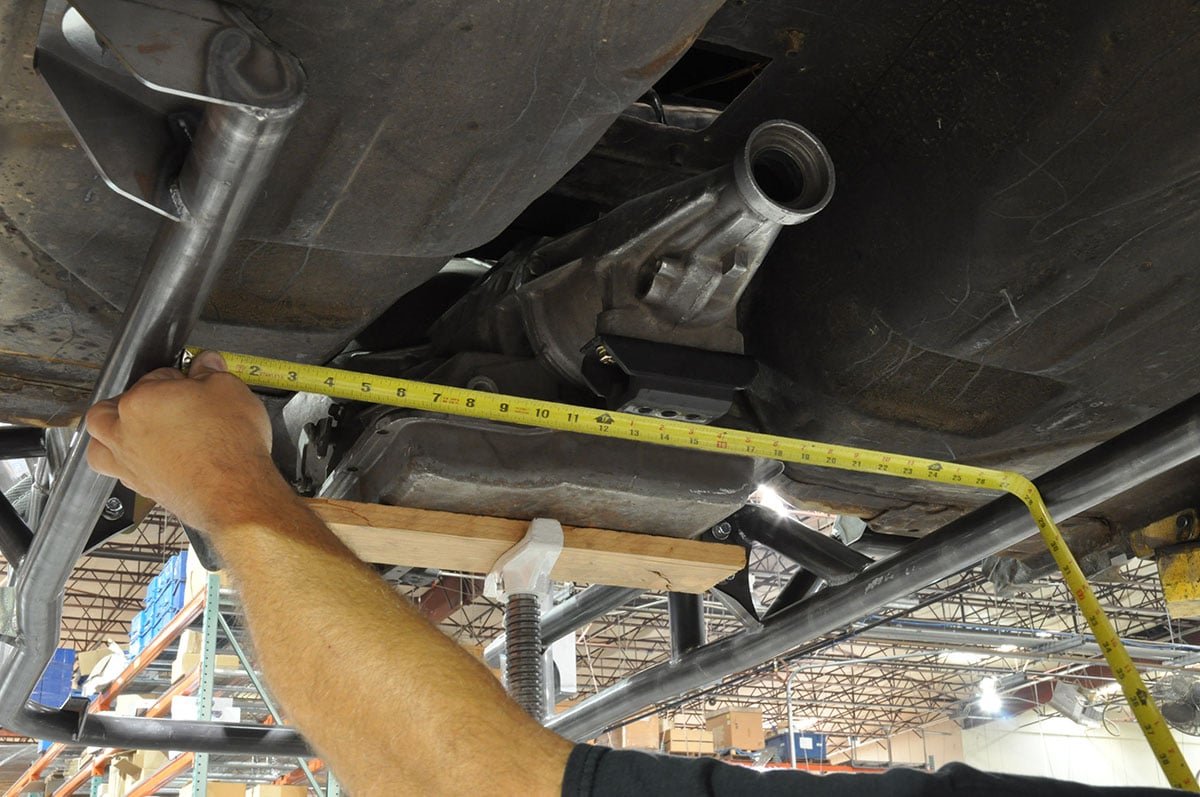
At first glance, Chassisworks’ new drag race clip is a solid front clip replacement that reduces weight and looks awesome doing it. Upon further examination, we found so much more. In addition to weight reduction, the people at Chassisworks worked hard to eliminate all the shortcomings of the OE front clip. They increased undercarriage clearance to allow for easy oil pan removal. They also increased front end safety and stability by improving suspension geometry.
They added versatility by dropping the double A-arm suspension and replacing it with a spring over strut configuration. The turning radius and steering responsiveness has been improved with a custom, in-house manufactured, rack and pinion steering system. In addition to all these improvements, Chassisworks made sure the front end would be fully compliant with SFI 25 series chassis certs as even the transmission crossmember has been engineered to the chassis crossmember specification.
 When we spoke to Chassisworks at the time of this writing, they had already sold several front ends, and were hard at work rolling new front ends off the assembly line to keep up with demand. These packages can be found in multiple configurations at their site, http://www.cachassisworks.com. The front end can be found HERE.
In our next strut feature, we will take a trip to the VariShock factory where the billet struts for this kit are made. Once there, we’ll dive into the inner workings of a high caliber drag race strut. We’ll take a look at the materials and follow the manufacturing process from the factory bench and assembly to sitting under the race car.