Is there anything more iconic about a muscle car than having a four-speed shifter protruding through the floor? While rowing gears yourself has given way to electronic transmissions, there are still many folks who like manually yanking a shifter for gear selection. But, there has to be a coupling unit between the engine and transmission. This coupling device (clutch) is a necessity for shifting. With the myriad of choices available, choosing a clutch can get confusing.
We recently did an engine swap in an A-body Mopar that saw the 340ci engine pulled in favor of a 360ci engine. The swap was straightforward, but the difference came about when it was time to install the clutch. The two engines vary greatly in regard to engine balance, requiring vastly different flywheels. Not only was the flywheel holding up completion, but we also needed to decide what style clutch would be best for our hot rod. We had questions, and the folks at SPEC Clutches and Flywheels had answers.
To begin with, that coupling unit known as the clutch is a wear item and is made up of several parts. Allowing gear changes is a flywheel, clutch disc, and a pressure plate. When the engine is running, the flywheel is spinning at the same RPM. Without a disconnect between the engine and transmission, putting the transmission into any gear is impossible while the engine is running. The clutch is the disconnect.
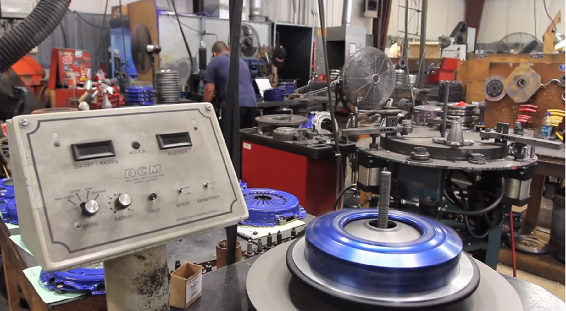
SPEC neutrally balances individual components (before adding any counterweight), so technically, the balance will be better than OE-spec, regardless of orientation. SPEC offers an even higher-quality balance by including an assembled balance.
A Question Of Balance
The balance problem we ran into, began with the flywheel. The 340 we removed was an internally balanced engine, and the 360 is externally balanced. Engine balance varies, due to the fact certain engines — like a 340 Mopar with a steel crankshaft — utilize a crankshaft that can be balanced by the counterweights alone. This is said to be internally balanced. But, if the connecting rods and pistons are too heavy and the counterweights are too light by themselves to balance the crankshaft, more weight is needed. This added weight is introduced by using a harmonic damper and/or flywheel that has weight added to it – externally balanced.
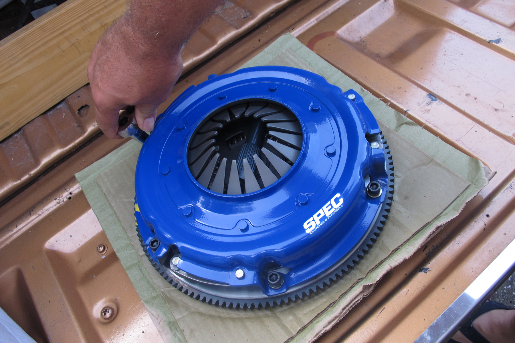
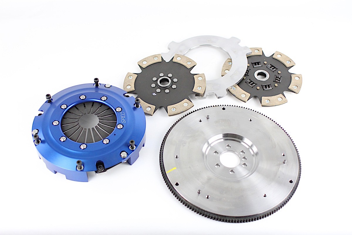
The swap in our Mopar to an externally balanced engine necessitated a new flywheel with the added weight. We were not comfortable purchasing a new flywheel and then installing a used clutch disc and pressure plate, so we contacted Dave Norton of SPEC Clutches and Flywheels. With his input, we decided to replace it all with a new flywheel (PN SD04S) and a Stage 1 (PN SD041) clutch disc and pressure plate.
The SPEC kits are a complete unit that can be ordered in configurations that meet any need. “The clutch material needed is definitely dependent on engine torque,” says David. “While the material will handle a good bit more, our Stage 1 kit is set up for engines with up to 485 lb-ft of torque, the Stage II is good for up to 558 lb-ft of torque, and Stage III is compatible with engines producing up to 660 lb-ft of torque. Stages I, II, and III also come in Plus (+) versions that can handle up 624 and 770 lb-ft of torque.”
The Stage 1 clutch kit we are using features an integrally molded carbon- and Kevlar-based, high-performance organic lining that offers smooth engagement and excellent life. This lining is bonded to a steel backing for strength under high clamp loads and temperatures. The hub comes in either sprung or rigid (we are using a sprung disc) and is application dependant. The double sprung hub features spring cover reliefs for flexibility, and both hubs use heat-treated components for strength and durability. This is SPEC’s best choice for a street car, and many track/off-road applications.
Each SPEC flywheel is neutral balanced, but a specific external-balance weight is attached depending on the application. This process means a single flywheel can be used for different applications of internal- or external-balance engines.
“Any of our stages through 3+ are considered ‘street-friendly’ units, though they are built for extreme application,” says David. “Stages 4 and 5, due to the rigid-hub configuration, are still streetable, but not street-friendly. In multi-disc applications, some of the rigid configurations are more street friendly due to the progressive nature of double and triple the surface area.
“Our Stage 3+ material is the flagship, offering the highest level of wear life, holding capacity, and drivability at its rating. The carbon/carbon friction material is the most advanced and costly to manufacture, offering an extremely lightweight option, high-torque capacity, unparalleled heat threshold, and softer engagement. The most valuable characteristic of the carbon seems to be its ability to dampen driveline shock under the most extreme engagements.”
Stage 1 Clutch Kits (left) feature an integrally molded carbon kevlar-based, high-performance organic lining that offers smooth engagement and excellent life. Stage 2 discs (center) feature segmented or a full-faced pure Kevlar disc with steel backing. This lining features excellent drivability like the Stage 1, but offers slightly longer life and higher torque capacity. The Stage 2+ (right) is a multi-friction disc in a full-faced configuration with carbon semi-metallic on one side and Kevlar on the other. This disc bridges the gap between Stage 2 and Stage 3, the 2+ offers drivability and engagement-quality characteristics of the Stage 2, but with a 15- to 20-percent-higher torque capacity.
Friction Materials
Although the Dart Sport we are working on has a mild-performance engine and will be mostly street driven, those enthusiasts with engines of increasing horsepower might want to consider different friction-disc materials. If you’re looking at purchasing a typical parts store friction disc, you’ll likely get a basic organic material. This is okay for normal driving conditions and usage in an OE application. But, as operating temperatures rise, or you place the clutch under high loads (which is usually accompanied by slippage), an organic disc’s clamping ability will fade. This is because the coefficient of friction drops off. In addition, at high RPM, and/or when they get hot, they tend to fail structurally.
The Stage 3 disc (left) features a carbon semi-metallic 4- or 6-puck (application dependent) and a sprung- or rigid-hub disc that delivers great drivability, life, and torque-holding capacity. The Stage 3+(middle left) is for high-powered street or race cars that require a manageable and friendly engagement. The Stage 3+ features a carbon semi-metallic full-faced material that offers unparalleled life, friction co-efficient, and drivability characteristics in a single package. Stage 4 discs (middle right) are a solid-hub version of the Stage 3. It is available in a 3-, 4-, or 6-puck configuration. A Stage 5 disc (right) has a full-metallic disc with the highest possible friction co-efficient. While it is usable on the street, it is not street-friendly.
Next in the hierarchy of friction-disc material is Kevlar. This material offers a much higher coefficient of friction than organic materials. Although a more durable material than organics, Kevlar is still compatible with stock flywheels and pressure plates. It makes a really good choice of material as an upgrade. Even though it is a better material for a friction disc, clutch engagement is akin to that of organic materials.
According to David, “an enthusiast can benefit from a multi-disc clutch when the capacity of a single becomes insufficient or when drivability of a sufficient single-disc unit has deteriorated to the point that the car is no longer fun to drive. The benefits of a triple-disc are threefold: higher capacity, rebuildability, and better drivability.”
If you are looking for something aggressive, bronze-metallic materials are an aggressive material used in clutch-friction discs. While it is a durable material, it will not resist wear as well as Kevlar. “Bronze metallic is a 30-year-old technology,” says David. “Instead, our Stage 3, Stage 3+, and Stage 4 all use a semi-metallic (carbon-graphite semi-metallic, specifically). It can wear as well as a fiber unit in daily use.”
Finally, sintered-iron is a material that is not the greatest for street use. It has a great ability to withstand some slippage and not lose its friction coefficient. Sintered iron is great for high-horsepower applications and for drag racing.
“The disc-material friction coefficient, coupled with the pressure-plate clamp load, surface diameters, configuration, and a few other factors, determine the torque capacity of the assembly. A more aggressive material will have a higher friction coefficient, and therefore, will hold more torque at the same clamp load. Generally, higher-friction coefficient materials produce reduced engagement quality. But, recent material technology has produced high-coefficient materials that are more manageable than old-school high-performance materials like ceramic and full metallics,” quoted David.
Multiple Choice
Not only do you have to make a choice in regard to what material to choose for your clutch disc, but you also need to decide if you need one or two — discs that is. A clutch is generally rated by its torque-holding capacity. A single-disc clutch will inherently have less holding capacity than a twin disc, based solely on its surface area. Twin-disc clutches are designed to have lower inertia but will have higher torque-holding capabilities. This is because they spread the load across more surface area. Twin-disc clutches tend to be noisier in comparison to their single-disc counterparts, simply because there are more plates and plate separators introduced into the package.

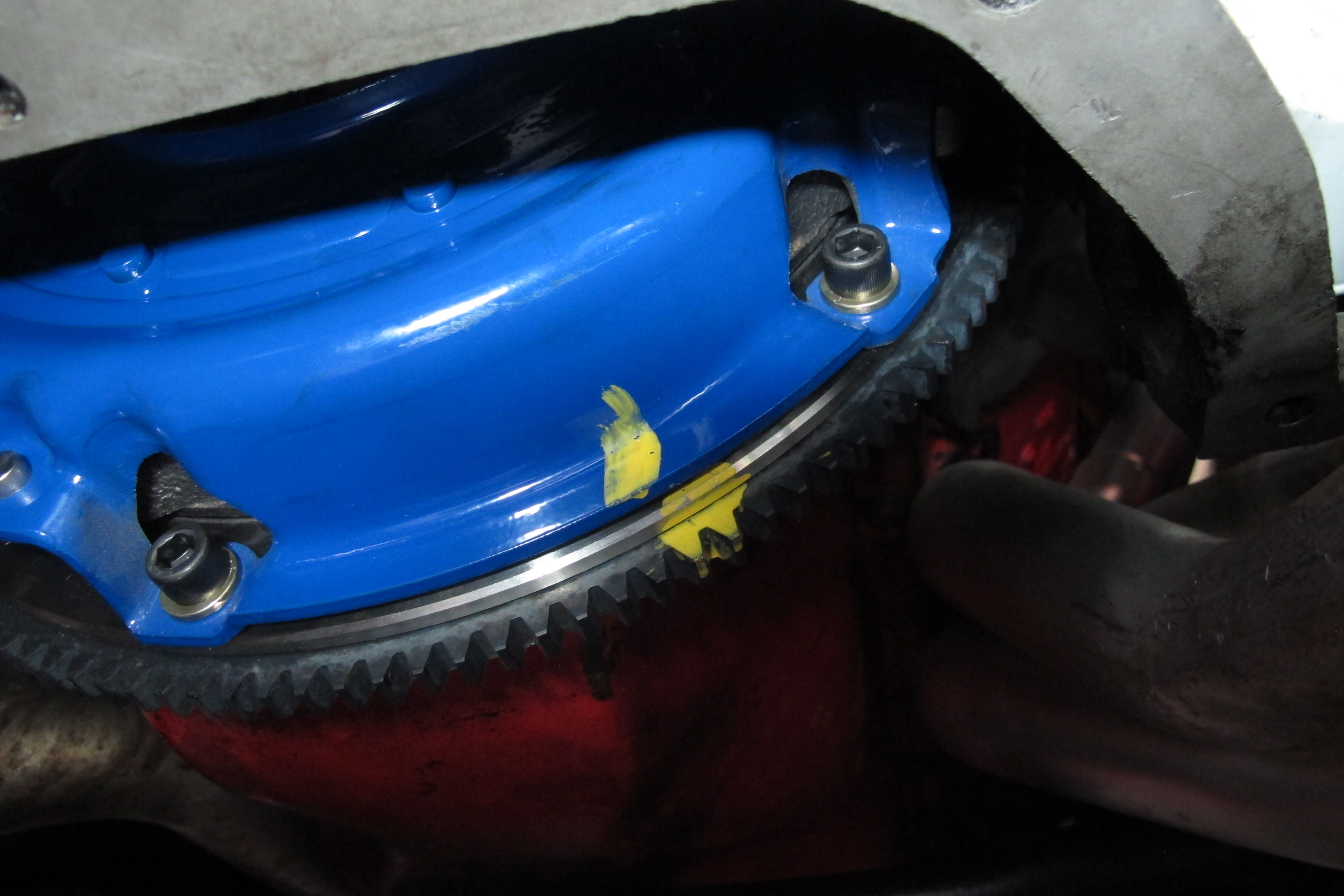
Not only does SPEC balance each part individually, but the assembly is then balanced as a unit. When the clutch system is installed with the marks aligned, a higher level of balance is achieved that exceeds OE.
A good rule of thumb to remember is that a single-disc clutch is a good all-around performance clutch with a stock or mildly modified engine. Depending on the clutch material used, it will have OE-like engagement and shifting qualities. Twin discs are designed to handle a lot more torque than a stock or even aftermarket single disc. Therefore, they are a better fit for higher horsepower applications.
Even if a single-disc clutch works in an application, it is considered insufficient if it experiences significantly reduced wear life. There are also cases where a single-disc system might have a sufficient torque capacity, but the overall setup can benefit from a smaller-diameter multi-disc unit to deliver better shifting capabilities and a lower-inertia clutch and flywheel package for a significant rate of RPM and horsepower gains. Deciding what is best for your application is easy to figure out with a call to the SPEC Clutches and Flywheels techline.
Weighted Rotation
When talking clutches, you have to factor in the flywheel. The flywheel not only has the teeth for starter engagement, it is also an energy-storing device. Not only will a heavy flywheel cause the engine’s RPM to climb at a slower rate than a lighter (aluminum) flywheel, but since it also stores more energy because of its mass, the engine’s RPM will not drop as dramatically (like between shifts) as it would if using an aluminum flywheel.
An aluminum flywheel (left) has a steel surface for the friction disc to contact. An aluminum flywheel will allow the engine to rev much faster than a steel unit (right).
On the other hand, a lighter aluminum flywheel will allow the engine to rev up much quicker, but a more dramatic drop in RPM will be noticed (like between shifts), and the lighter weight could also cause an issue when daily driving your car. This issue is because the lower inertial mass of the lighter (aluminum) flywheel means that the car could be harder to get moving from a stop sign or traffic light. Aluminum is generally used in road-race/drag-race applications where the engine is kept at higher RPM.
The billet unit that came with our clutch kit was externally balanced by an add-on weight attached to the backside of the flywheel via screws. This form of balance adjusting means the flywheel can also be used in an internally balanced application by simply removing the add-on weight.
Under Pressure
Without a pressure plate, your clutch will not work — period. The pressure plate is what applies and releases the clamping force that squeezes the friction disc. But, just like the flywheel and clutch disc, you have a choice to make. For this article, we’ll focus on the three main types of pressure plates: Long style, Borg and Beck, and diaphragm.
The Long-style pressure plate is identified by the three fingers that contact the release (throw out) bearing. This style of pressure-plate is typically used in drag-race applications and will have a hard-pedal feel — relatively speaking.
The Borg and Beck style is similar to the Long style, and while it too functions via three fingers, they can be identified by the somewhat-wider three fingers that release plate pressure. The Borg and Beck also uses rollers under the pressure plate cover that are forced outward under centrifugal force. This increases the plate-clamp load (pressure), with the increasing engine RPM.
Finally, is the diaphragm pressure plate. A diaphragm pressure plate uses a series of fingers (also called a Belleville spring), that completely encompasses the center opening of the pressure plate. The main advantage of this style of plate is that holding the clutch pedal down at a stoplight is much easier than with either a Long- or Borg and Beck-type pressure plate.
SPEC pressure plates are a centrifugal design, which offers great clamping ability with a relatively easy pedal feel.
Installing The Clamp
We were fortunate, in that our engine didn’t have a flywheel or clutch to remove. We were starting from scratch. But, before any work can begin, we took the time to inspect both the flange on the crankshaft and the mounting surface of the flywheel — you never know what you might run into. Make sure there are no burrs that might prevent the flywheel and the crankshaft flange from evenly mating. When installing the flywheel, do not use air tools. You might be tempted to shave a few minutes off the install time, but it could cause you an issue later.
Once the flywheel is in place, be sure to wipe off the contact surface of the flywheel and pressure plate with acetone or brake cleaner to remove any grease or rust-preventative coating. Before placing the clutch disc on the flywheel, slide it on the input shaft of the transmission and make sure it slides back and forth. Next, place the disc against the flywheel (flywheel side marked), and insert the disc alignment tool through the disc splines and press the tool firmly into the pilot bearing/bushing. This should hold the disc in place while you position the pressure plate. Place the pressure plate against the clutch disc and insert the bolts by hand. Insert all of the bolts before you begin to tighten them in a star pattern by hand.
Tighten the pressure plate bolts evenly and slowly using a star pattern. Do not tighten any one bolt all at once, and do not use air tools. Improper tightening will bend the pressure plate. Work your way around the pressure plate, slowly tightening each bolt several times until completely torqued. As you tighten the bolts, you will notice the fingers of the pressure plate traveling inward. You want this progression to be as even as possible. If this step is not done correctly, the clutch will not release properly, which can cause improper engagement of the clutch.
When tightening the pressure-plate-to-flywheel bolts, do not fully tighten one bolt and then move to the next. Tighten each bolt very little at a time until you have tightened them all. Do not use air impact tools. Once the bolts are tight, torque them to the vehicle manufacturer’s specifications. Remove the alignment tool. David agrees, “the SPEC kit requires OE bolt-torque values. We do recommend a dab of Loctite on the clutch to flywheel bolts only. Obviously, follow the known mechanical process, like torquing the pressure plate in a crossing pattern, a few turns at a time.”
Choosing the correct clutch is not a hard or confusing proposition. But, if you have questions, do not be afraid to ask. Manufacturers like SPEC Clutches and Flywheels are more than happy to help you make sure you get exactly what you need the first time.