Ed Note: The author would like to thank Jack Kane of EPI Inc for his contributions about flat-plane dynamics to this article.
The new LT6 Corvette’s flat-plane crankshaft engine that Chevrolet recently debuted has redirected a significant amount of attention on 180-degree crankshaft engines. We wrote a story for EngineLabs (“The Reality Regarding Flat Plane Crankshafts”) on this topic that generated enough interest that our mechanical engineer friend, Jack Kane, has run through an example of the forces created by this combination based on a few assumptions of reciprocating mass and rod length.
As you may recall from our previous story, the issue with flat-plane crankshafts is the inherent secondary vibration created by this design. The following discussion will explain using calculations to reveal these forces in a V8 engine using a flat-plane crankshaft.
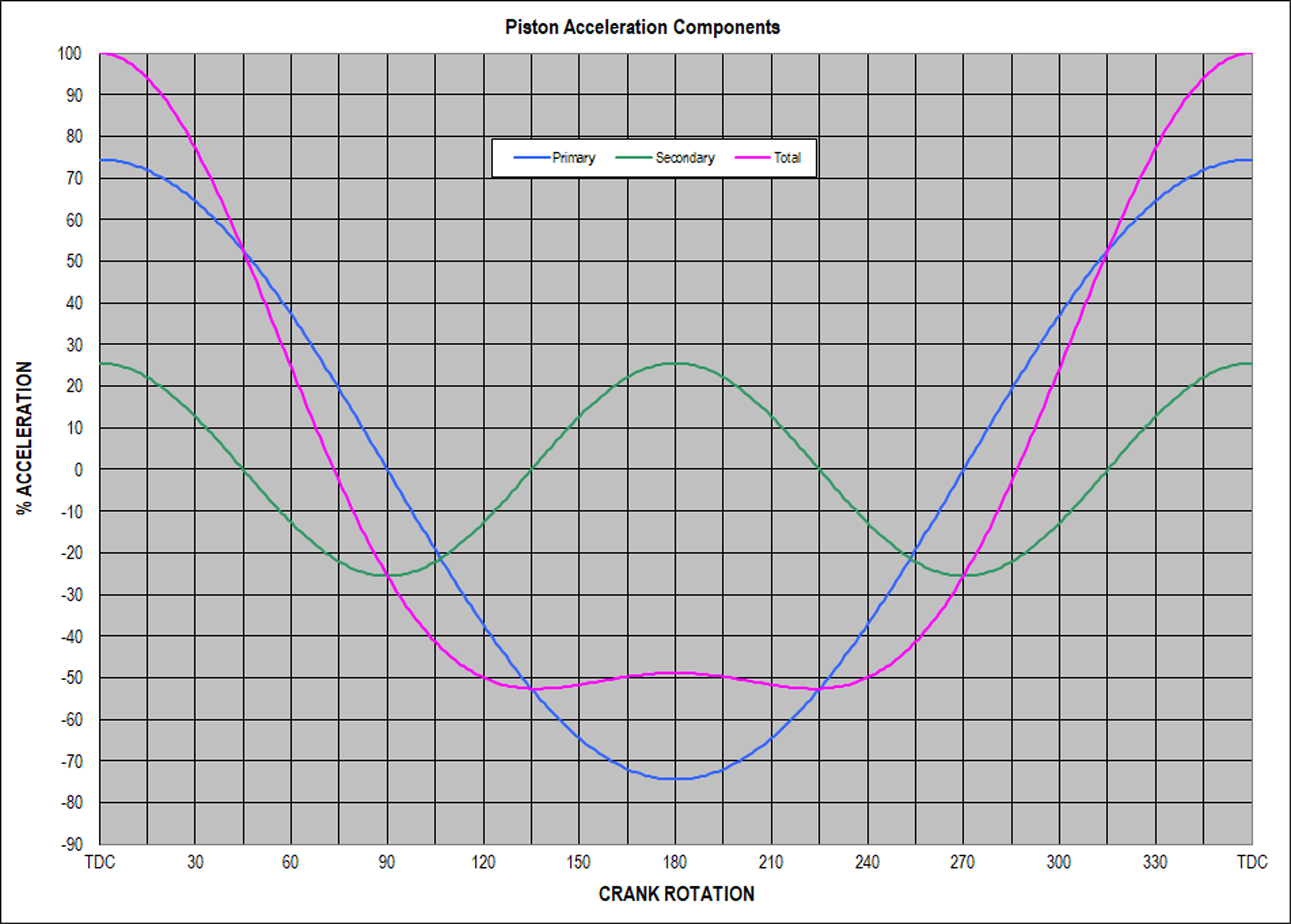
This graph by Jack Kane shows the different forces of both the primary (in blue), and secondary (in green) along with a third trace (in pink) that is the total of the combined forces.
Diving Into Flat-Plane Math
If we revisit Graph Number 1, the secondary forces are at their maximum “up” value (on the cylinder axis) at TDC and BDC and their maximum “down” value at 90 ATDC and 270 ATDC (90 BTDC). That explains the direction of the S1 and S2 vectors shown in the following diagrams.
In the following four diagrams, each shows the crank in one of four different positions: 0 degrees (AA), 90 degrees (BB), 180 degrees (CC), and 270 degrees (DD) relative to the cylinder on the right of each diagram. In each position, the secondary vibration forces are labeled S1 and S2. The “H” and “V” subscripts refer to their horizontal and vertical directions, respectively.
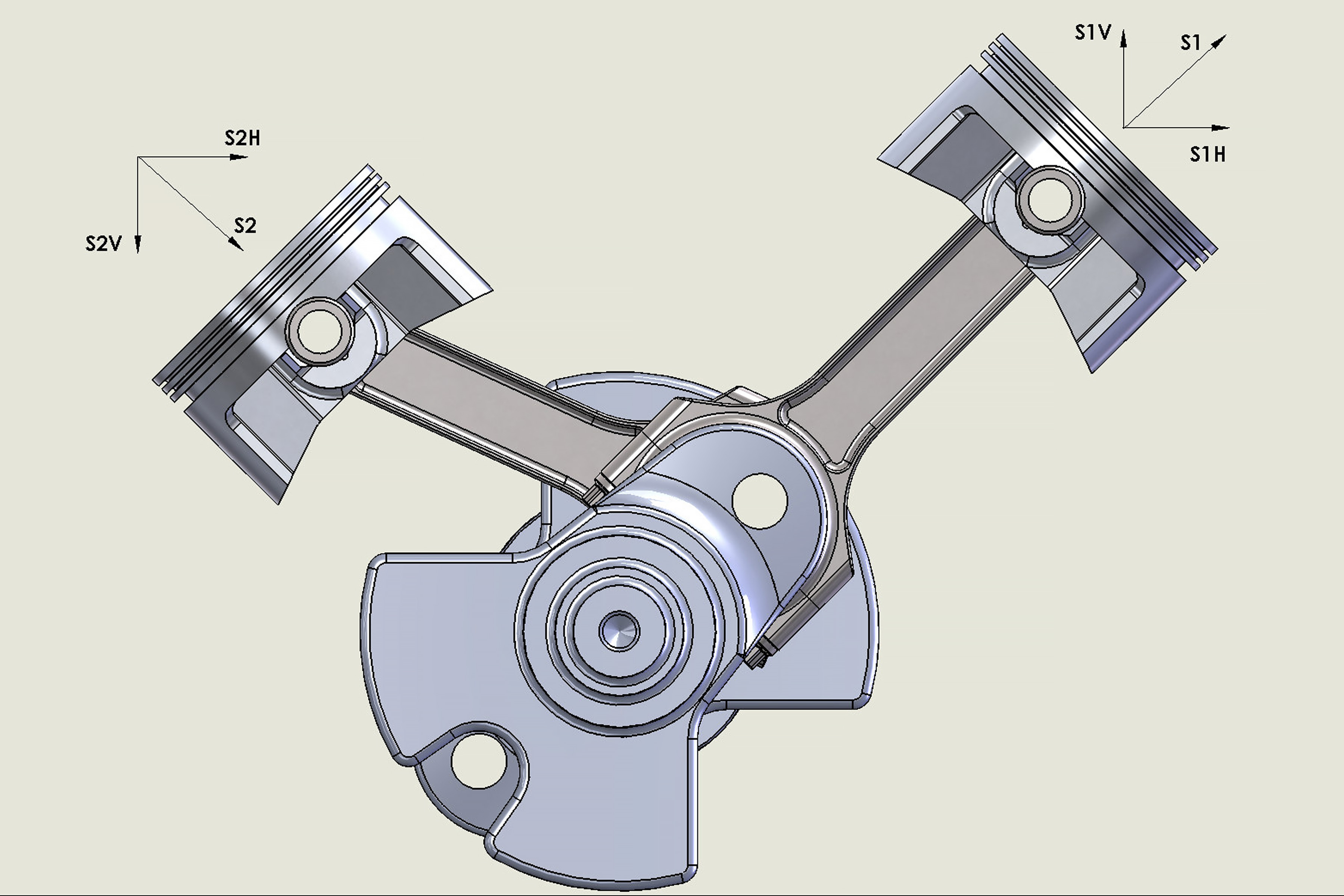
ILLUSTRATION AA — With the piston on the right side at Top Dead Center (TDC), the arrows indicate force directions. Note how the vertical (relative to the cylinder centerline) arrows cancel each other out but that the horizontal arrows (S1H and S2H) both point to the right. Compare this with illustration CC.
The S1 and S2 designations (and arrows) refer to the amplitude of the secondary acceleration force generated by the specific piston and rod reciprocating assembly when the components are in the positions shown. Those secondary forces (S1 and S2) act along the axis of the respective cylinders.
Any force vector can be replaced in an analysis by its correct vertical and horizontal components. In this case, since the secondary force vector is 45-degrees from both the vertical and horizontal axes (coincident with the axis of the relevant cylinder), both the vertical and horizontal components (S1V, S2V, and S1H, S2H) are equal, and their value is 0.707 times the S1 (or S2) magnitude. This number is the value of both sine and cosine of 45 degrees.

ILLUSTRATION BB — With the crankshaft now 90 degrees ATDC compared to illustration AA, the horizontal force vectors (S1H and S2H) now point to the left. Compare this with illustration DD and it becomes clear that there are large forces acting on a horizontal plane in both directions.
Just to add a bit of clarity, in a V12 engine with a 60-degree block and a 120-degree crankshaft, the TDC secondary vector (along the cylinder axis) would resolve into a vertical component of 0.866 of the force vector (cosine 30 degrees) and a horizontal component of 0.50 of the force vector (sine 30 degrees).
Illustration AA shows one rod journal for a 90-degree V8, with the right-bank piston at 0 degrees (TDC) position. Note how both horizontal components for both cylinders on that crankpin are in the same direction to the right. Illustration CC shows the same vector resolution occurs at the BDC position.
With a flat-plane V8 crank, in one bank, two cylinders are at TDC while the other two cylinders are at BDC, while the corresponding cylinders in the opposite bank are at the mid-stroke positions (see the lead photo).
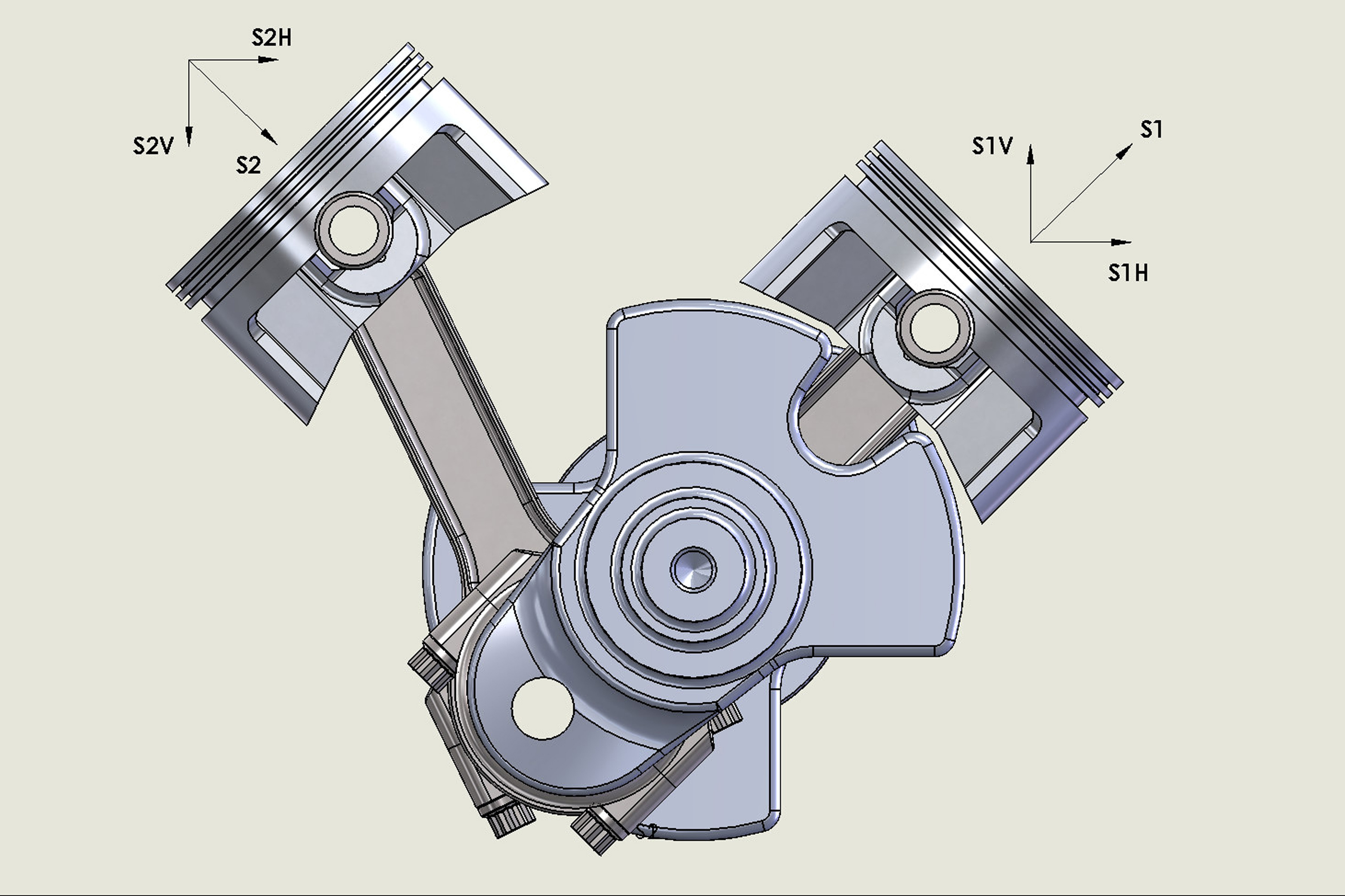
ILLUSTRATION CC — As with illustration AA, note how the horizontal force vectors both point to the right, 180 degrees after the position of illustration AA.
So, while the vertical values cancel each other out, the horizontal components of all 8 cylinders add together to produce a large horizontal force as shown, pointing to the right in the diagrams AA and CC. When the other bank is at TDC/BDC, the mirror image vector resolution occurs and now all 8 cylinders are added together to produce a large horizontal force to the left.
Although the secondary magnitude is a relatively small fraction, ranging from extremes of 15- to 25-percent based on rod-length-to-stroke ratios (R/L), when they add together, the magnitude becomes 8 times 0.707 times the secondary magnitude. Using a secondary peak that is 20-percent of the primary peak, then the additive horizontal magnitude becomes the following value:
Primary force vector magnitude x 0.20 x 0.707 x 8 = 1.13 times the primary force vector magnitude. Remember that those 15- to 25-percent numbers are a percentage of the peak primary piston acceleration values.
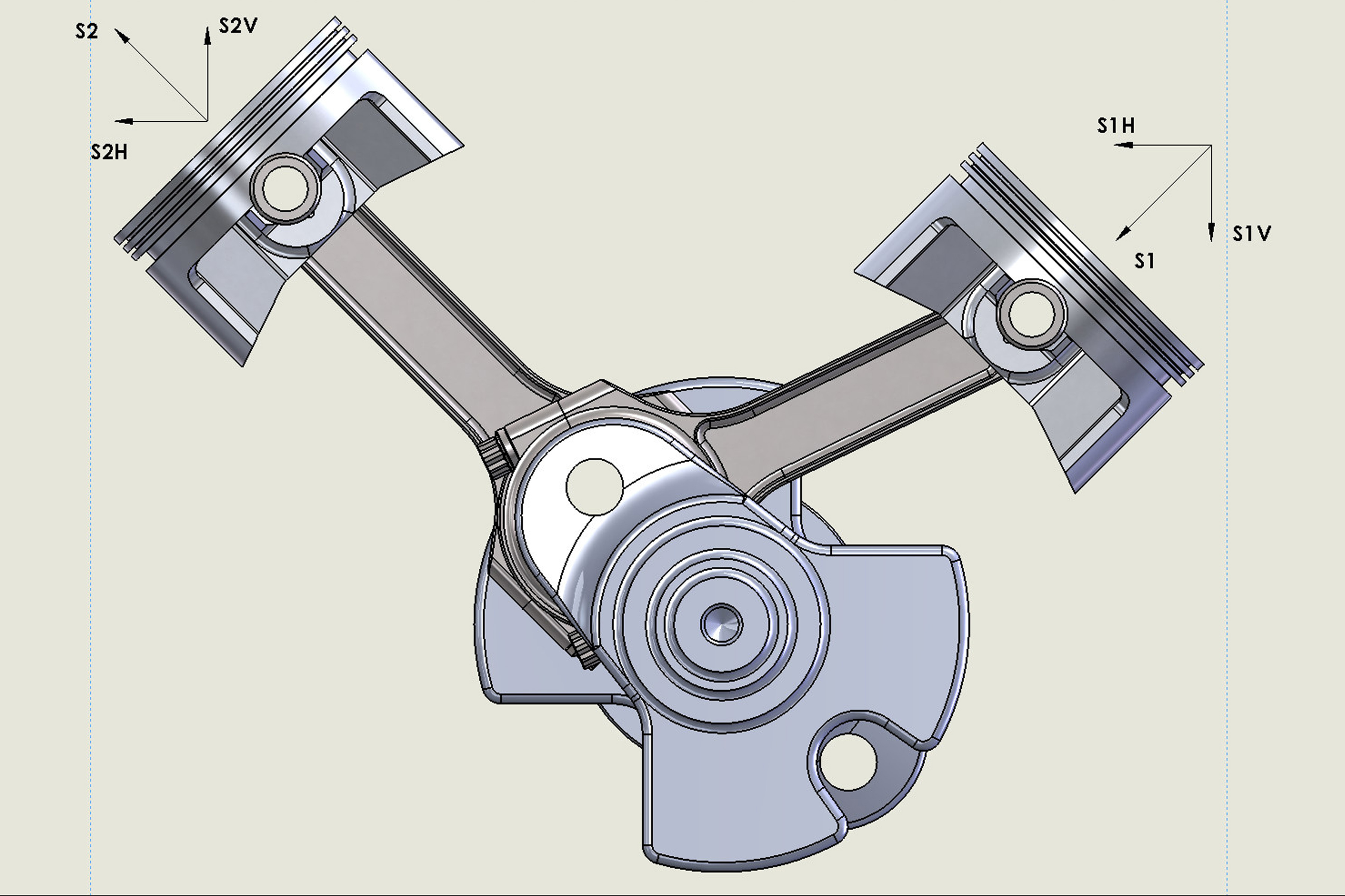
ILLUSTRATION DD — Again, the horizontal forces show a force vector to the left with the crankshaft having turned 280 degrees from its original position with a horizontal force direction to the left.
Practical Application
For the LT6, let’s assume a piston and pin weight of 550 grams and a rod small-end weight of 200 grams. We’ll also use a stroke of 3.150 inches with a rod length of 6.333 inches. At 3,000 rpm the peak primary piston acceleration at TDC is 504g, for an upward force of 830 pounds at TDC. With this R/L ratio, the peak secondary value is 19.92 percent of the primary peak, or 165 pounds. That produces a horizontal shake force of 1.13 x 830 = 933 pounds.
However, when we double the speed to 6,000 rpm, the peak primary acceleration is 2,011g, for a peak primary acceleration force of 3,319 pounds (upward, at TDC). So at that RPM, the peak secondary value is 661 pounds (19.92 percent of the primary peak), and the horizontal shake force at 6,000 rpm becomes 1.13 x 3,319 = 3,750 pounds — or four times the force occurring at 3,000 rpm. This clearly illustrates the effect of RPM — doubling the speed quadruples the inertia force.
Again, these forces are calculated based on some assumptions since the true reciprocating mass and rod length numbers have not yet been revealed by GM. These numbers do put in real force terms, the value of the secondary vibration inherent in a flat plane crankshaft. So, while flat-plane crankshafts seem like the latest and greatest, there are real, measurable side effects that come with the design.