Bolted on the bottom of your engine block is a motor assembly that rarely gets the respect it deserves. You never hear someone talk about how fantastic their starter is, yet that compact electric assembly is tasked with taking the weight of a static crankshaft and rotating assembly to a spinning and running engine at a moment’s notice. These starter installation tips will ensure your part works optimally and lasts a long time.

Today’s performance starters are designed and built to handle this thankless task over and over — when installed correctly and wired properly. Like any component of the drivetrain, if it is not installed properly, there may be issues or even damage to the part. In most cases, installing a starter is a pretty straightforward process with a couple bolts and two or three wiring connections, but there are several important specifications to check and consider during the installation.
We talked with the starter experts at Powermaster about the proper procedure for installing a block-mounted starter. We’ve worked with them before and the results have always been exactly what we hoped for — or better. Powermaster has over 30 years of experience designing and manufacturing starters so they’re very familiar with the process of checking pinon depth, gear mesh and cranking voltages.
These checks don’t take long and are easy to set up properly, but it’s amazing how many people may simply skip right over these important checks.
Following these steps will ensure your starter delivers the performance and longevity that you expect.

Installation Tips

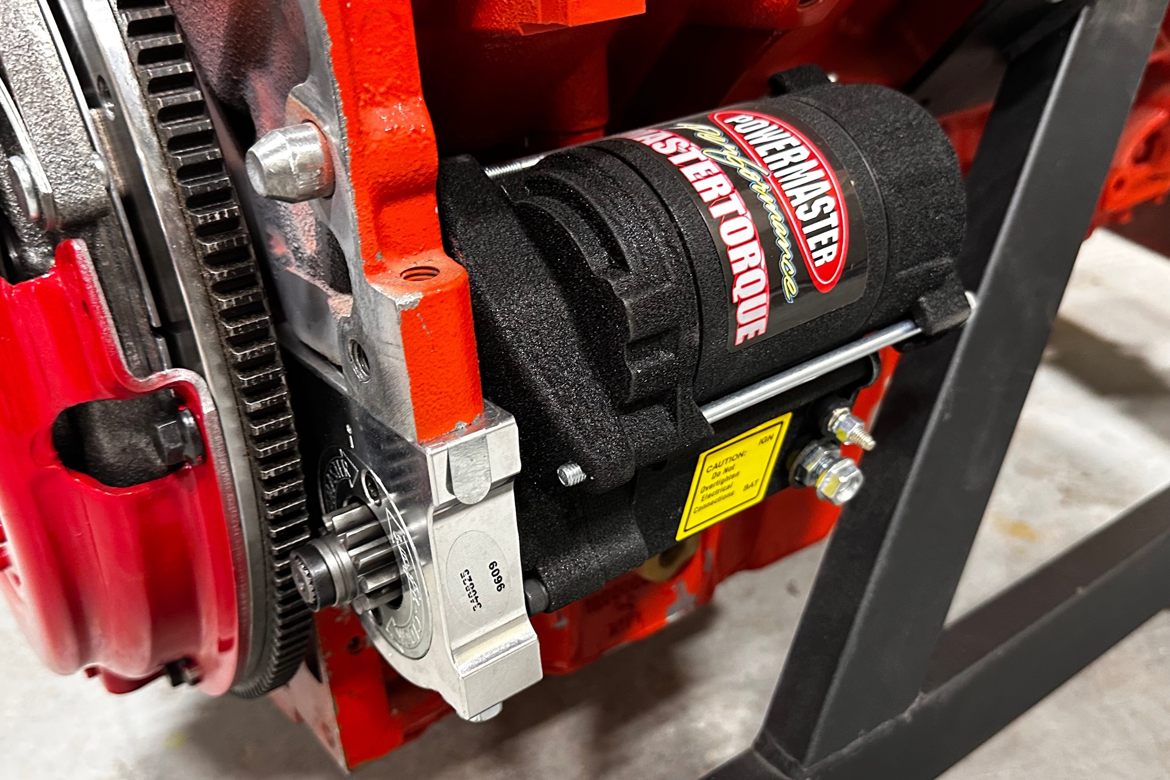
If your new starter came with mounting bolts, use them. Powermaster supplies special fasteners for a reason. These long bolts feature a knurled shaft which helps keep the starter from moving while they’re cranking. Smooth shaft bolts will allow the starter to flex or move a tiny amount, which will grow over time until there are issues. Always use the correct hardware.
Mounting Surface

The starter motor uses a lot of current, which means there must be a clean, clear ground path. The mounting pad must be clean of paint and grime so there is a quality ground path. And be sure to have a ground cable from the block to the battery negative terminal.
Three Specs To Confirm
The big three measurements to check include: Ring Gear Clearance, Pinon Depth (in and out) and Gear Mesh (up and down).
Check Ring Gear Clearance: Once the starter is installed to a clean mounting surface using the right bolts, confirm that there is about .100 – .125-inch between the pinion gear and the ring gear. It’s recommended to check in three-four locations by rotating the ring gear.

Check Pinion Depth: The pinion depth is the distance that the pinion gear teeth engage into the ring gear teeth. A rule of thumb is to have the 50-75 percent of pinion gear teeth engaged into the ring gear. This can be checked by pulling the pinion gear out of the starter and engaging it into the ring gear. If access to the pinion gear is limited, coat the pinion gear with Marking Blue compound and spin the engine over.
It is best to check the depth in at least three positions on the ring gear to ensure a straight flexplate. If the pinion gear engages too much or is too deep into the ring gear, the starter gear could hang up, grind and get over-revved when the engine starts, causing serious damage to the starter. Keep in mind, between the ring gear and starter gear is a 30:1 ratio — imagine the carnage to a starter if the pinion gear were to get hung up.

To solve excessive engagement, Powermaster supplies a shim that goes behind the mounting block of the starter to help achieve the proper gear depth. It is very rare to have too little engagement, which would lead to requiring machine work on the starter block.
Check Pinion Gear Mesh: Gear mesh is the relationship of the ring gear and the pinion gear teeth. There should be .020 – .035-inch of area (the size of a paperclip) between the ring gear teeth and the pinion teeth when engaged. If the clearance is too tight, shims can easily be added between the engine block and starter mounting block. Most starter companies supply a couple shims that fit between the mounting block and the engine mounting pad.

Electrical Connections
Once you’ve got your mechanical checks in spec, the last thing you need to consider is the electrical side of your installation. The most important parts to consider here are the quality of the cable, the length and gauge, properly crimped terminals and the amount of voltage present at the starter during cranking.
Cable Gauge and Length: If you’re working on a performance application, there is absolutely no reason to use the stock starter cables. Consider that a starter can pull up to 500 amps during cranking which stresses every component of the starter system including the cable, terminals and disconnect switches. If the cable and terminals are not up to the task, voltage will drop, amperage draw will increase adding more heat to the system and eventual failure. Powermaster offers different lengths and gauges multi-strand copper cables to ensure you have the best connection to the starter.
The length of the cable will have an effect on the gauge cable required. If the battery is in the trunk, Powermaster recommends a -2 to 0 gauge cable. Shorter cables, such as when the battery is mounted in the engine compartment, could be -4 gauge. Check out the chart below:

The S-Terminal (ignition) Wire: The wire that connects to the S terminal, the wire from the ignition switch that activates the starter, should be inspected and is best to simply replace it on older applications. This wire may draw up to 15 amps, depending on the starter, and Powermaster recommends at least a 12-gauge wire be used.

Cranking Voltage: Once everything is installed, Powermaster recommends checking/confirming the voltage at the starter during cranking. They recommend at least 11 volts on both the battery terminal and the ignition terminal during cranking. (This is one of the first things Powermaster asks if you’re having cranking issues.) With a fully charged battery and proper cables/wiring, there should be over 11 volts during cranking. If the voltage is less, it could cause the solenoid to draw higher current resulting in chattering, erratic operation and excessive heat which will damage the solenoid. Powermaster provides a Tech Bulletin about how to check this voltage with all of their starters and has a helpful video on their YT Channel.
You might also like
GM Finally Confirms Chevy Camaro Replacement Details
General Motors officially approved an upcoming Chevy Camaro replacement. The brand new model begins production late 2027 in Michigan.