Project Mighty Mouse, our high-winding small-block 327, is sunsetting its days on the engine stand. This week, we wrapped up the SBC rocker arm installation, the final big installation on this build. After this, all that is left are things like the distributor, carburetor, and a few other minor odds and ends. For those just joining us, Project Mighty Mouse is a 1977 Chevy Nova. It came to us wearing a modest 250 ci inline-six from the factory. We have been replacing that with a high-revving 327 small-block built to keep making power well past 6,000 rpm.
What A Proper SBC Rocker Arm Installation Requires
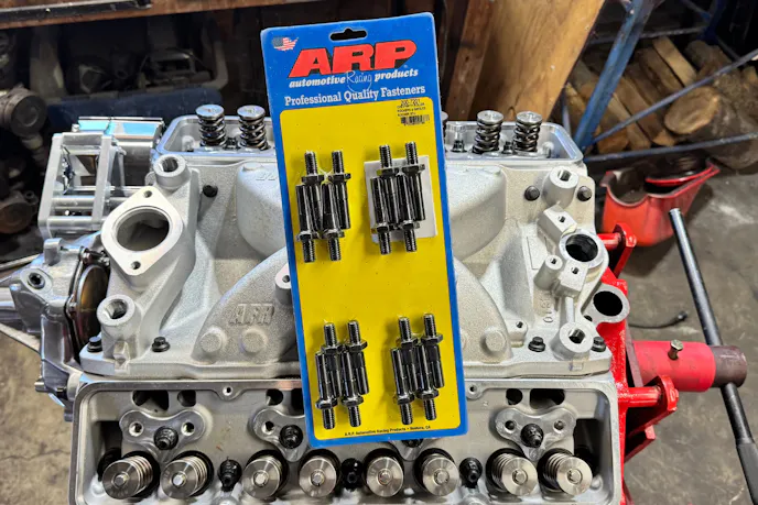
Before any rocker arm went near the engine, we made sure the foundation underneath was solid. We installed a set of ARP 7/16 rocker arm studs (P/N 200-7201). ARP machines these Pro Series studs from 8740 chromoly steel and rates them at 190,000 psi tensile strength. They are concentric within .005 T.I.R. thread pitch to thread pitch. That means they go in straight and true every time and deliver consistent rocker geometry from the start.
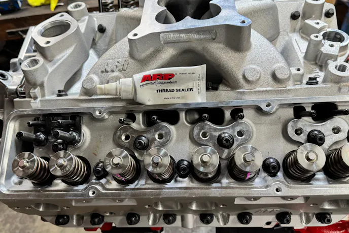
On the intake studs, we applied ARP thread sealer before threading them in. Those studs pass into the intake ports. Without a sealer, oil can creep down the threads and drip where it absolutely should not.
Measuring Pushrod Length The Right Way
Properly measuring pushrod length was one of the most important steps in this entire process. Guessing is never a good idea, but it is especially risky when you run retrofit hydraulic roller lifters like the ones on this engine. The geometry differs enough from a flat-tappet setup that a stock spec or a ballpark figure will not cut it.
To measure correctly, we used the Howards Cams mockup rocker arm (P/N 92138) and the adjustable pushrod checker (P/N 92129). We also pulled some lightweight valve springs from our Jegs Cam Degree Kit. Those lightweight springs let us rotate the engine over with the adjustable pushrod in place. The actual valve springs generate far more force than the adjustable tool can handle, so using lightweight springs protects the tool from breaking.
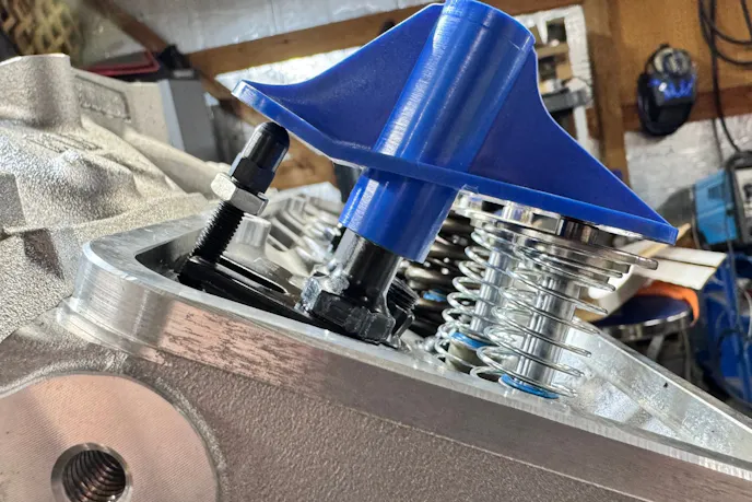
Here is a useful trick: Remove the Schrader valve from an engine compression tester and fill the cylinder with compressed air. You can then remove and install valve springs with the cylinder head still on the engine. The air holds the valve up. It keeps the valve from dropping into the cylinder while the spring is off. This method pairs well with the Preform valve spring compressor (P/N 66784), which mounts directly to the stud and compresses the spring on the engine.
Reading The Valve Contact Pattern
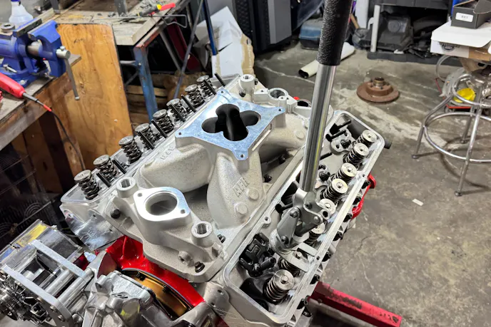
With the lightweight springs in and the adjustable pushrod sitting in the lifter, we used the mockup rocker arm to find the correct height. We adjusted the length until both ends of the mockup arm sat squarely on the pushrod and evenly across the valve tip. Once that looked right, we swapped in an actual roller rocker arm. We also marked the top of the valve stem with a Sharpie to track exactly where the rocker tip contacted it.
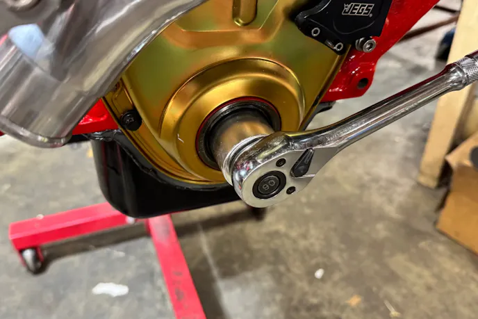
We then rotated the engine over seven to eight times to generate a clear contact pattern. The goal is to see that mark land in the center of the valve tip. A mark reading toward the intake manifold side meant we needed to extend the pushrod. A mark toward the exhaust side meant we needed to shorten it. Even a micro-turn on the adjustable tool can shift the contact patch more than expected, so this step takes some patience. Eventually, we landed on a mark we were happy with. The adjustable pushrod measured 7.450 inches at that point. With 0.100 inch of preload factored in, we needed a 7.550-inch pushrod. We placed the order and waited.
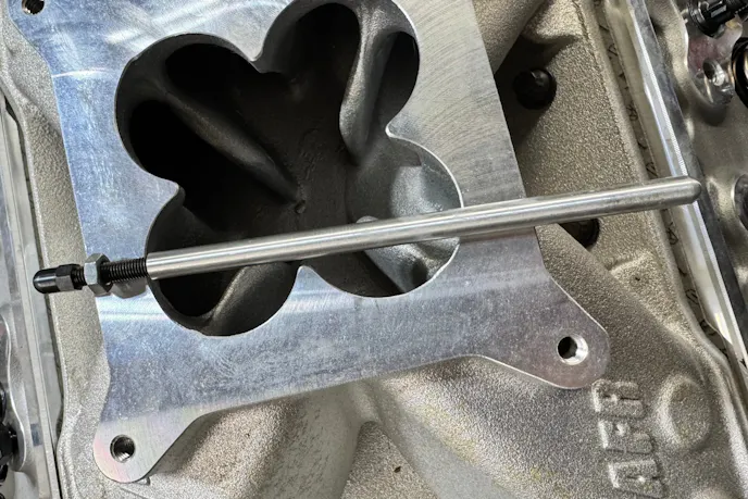
Installing The Guide Plates
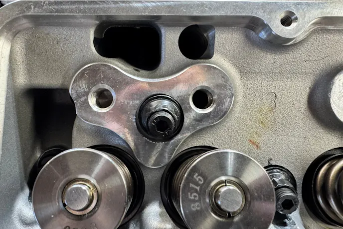
Underneath the studs sits a set of AFR adjustable pushrod guide plates. One important note here: if you run guide plates, do not run self-aligning rocker arms. The two setups are not compatible. The guide plates handle alignment themselves. Self-aligning rockers are not only unnecessary in this setup, but they are also counterproductive.
Once the correct pushrods arrived, we moved into the final installation of all the rocker arm studs and guide plates. This step demands patience. Getting each guide plate into position is genuinely tedious. The goal is a sweet spot where the pushrod moves freely through the slot without binding. Moving one plate slightly almost always nudges the one next to it. You end up making small adjustments on both the intake and exhaust sides of the same cylinder. Once you get both lined up, you have to torque the stud down without letting the plate move.
We are seriously considering tack-welding the guide plates together before we seal this engine up. That would stop them from loosening or shifting once the engine is running. It is a small extra step, but it could prevent a real problem down the road.
Setting Rocker Arm Preload
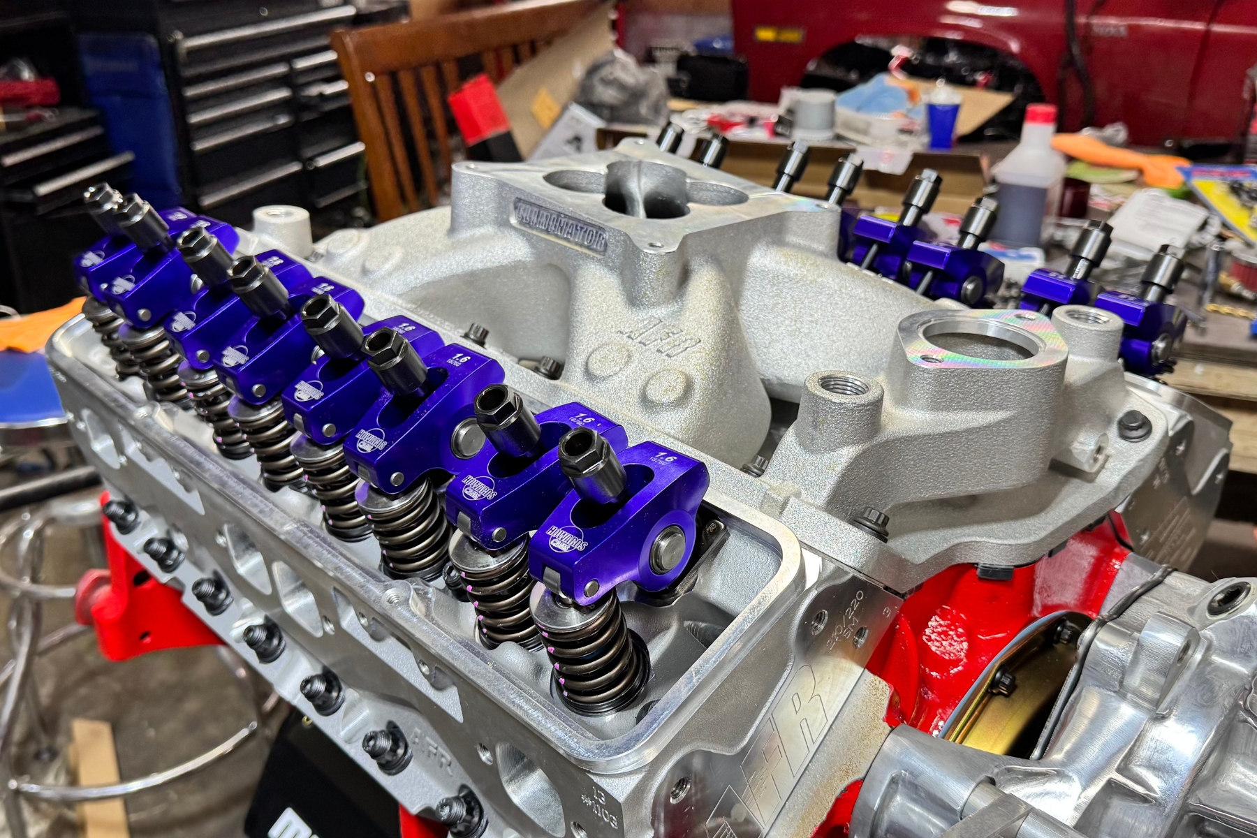
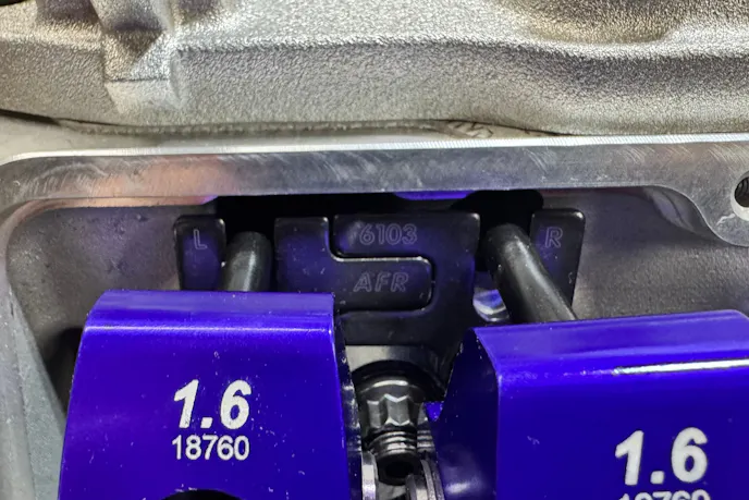
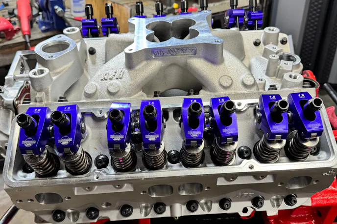
To keep up with the high-rpm demands of this build, we turned to Howards Cams for a set of 1.6 roller tip rocker arms (P/N 90073). Howards Cams makes these in the United States for Chevy 265-400 small-blocks. They are stud-mounted billet aluminum rockers with a 1.6 ratio, a 7/16 stud size, polylock nuts, and a purple anodized finish. Cam Motion recommended a 1.6 ratio when we spec’d out the camshaft with them, so we matched the rockers to their spec.
With the guide plates locked in, we moved on to setting the rocker arm preload. Builders debate this topic, and methods vary. Here is the approach we used for our SBC rocker arm installation.
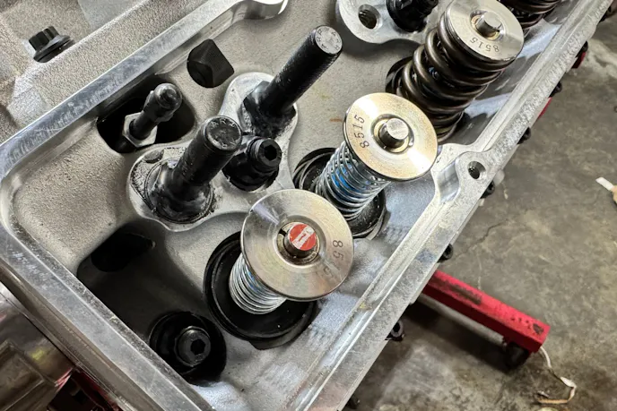
First, bring the engine to Top Dead Center (TDC) in the firing position for cylinder number one. From that position, adjust these valves: Exhaust 1, 3, 4, and 8, and Intake 1, 2, 5, and 7.
For each valve, back out the rocker arm nut until you feel lash at the pushrod. Then turn the nut back in until you remove all the lash. Spin the pushrod between your fingers while you slowly tighten the nut. When the pushrod stops spinning freely, you have hit zero lash. Turn the nut an additional full turn to set the preload.
Next, rotate the crankshaft one full revolution to bring the engine to TDC on cylinder number six. From that position, adjust the remaining valves: Exhaust 2, 5, 6, and 7, and Intake 3, 4, 6, and 8. Follow the same process on each one.
Bolting On The Stud Girdle
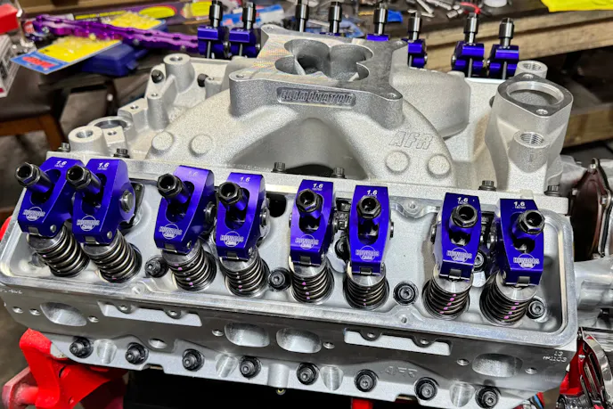
With the rocker arms set and preload dialed in, we bolted on the Howards Cams Maximum Effort rocker arm stud girdle (P/N 90101). Howards Cams makes this girdle in the USA from aluminum with a purple anodized finish to match the rockers. It fits Chevy 262-400 engines, uses a 7/16-20 lock nut, and includes the lock nuts.
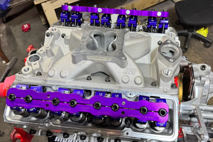
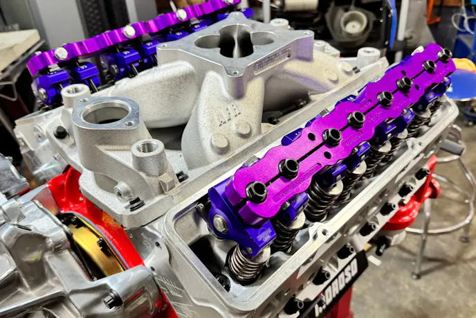
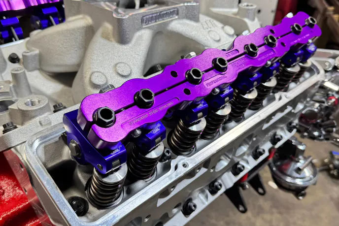
A stud girdle is easy to overlook on a street build, but it earns its place on a high-rpm engine. Without one, each rocker arm stud flexes independently under load. That flex shifts rocker geometry and changes the contact patch on the valve tip. The girdle ties all the studs together, stops that movement, and keeps geometry consistent across all eight cylinders. On an engine built to live past 6,000 rpm, that consistency matters every time you bury the throttle.
What’s Next For Project Mighty Mouse
With the valvetrain fully assembled, this 327 looks and feels like a finished engine for the first time. From the bottom end we built earlier in the project to the AFR cylinder heads, the Cam Motion roller cam, and now the complete SBC rocker arm installation, every major piece is in place. All that stands between Project Mighty Mouse and its first startup is a short list of finishing pieces. The distributor and carburetor go on next, and after that, it is time to hear this thing run for the first time. Stay tuned.
You might also like
Pure Pontiac Power Pushes ’65 GTO To Streetable 8-Second ETs
Pure Pontiac People, we have found your hero. This GTO run a best of 8.28 at 174 mph, but it does it with real Poncho power and a stick.