We’ve been bringing you our weekly build updates for Project FFR Cobra Jet Challenge, our build-it-yourself kit car from Factory Five Racing (FFR). The build is on a fast track to get it completed by SEMA, and we’re well into the project by now with every spare hour at home being spent on putting this life-size model kit together. A few weeks ago, we brought you the chassis and delivery process, and filled you in on the project in general. The first order was removing the body and laying out the panels – and marking them with location and direction for future reference when it comes time to reinstall them.
The next step was assembling the front suspension on the Challenge Car, FFR’s race-inspired chassis and suspension. While the Mk4 Roadster can be taken to a track, the Challenge Car goes a little further with protection and support to handle competitive racing on a regular basis. Unlike typical model kits that we built as a kid, the choices for the FFR kits are not limited to cosmetic differences, the suspension can be built and custom-tailored to the car owners needs.

Front Control Arms And Sway Bar

The lower control arms are available with three choices for the Mk4 and Challenge car, with two mounting locations based on the arms used. The arms are based on 1987-’93 and 1994-’04 Mustang, or FFR’s tubular control arms, and are mounted according to the instructions with the kit. The lower ball joints arrived installed, but the bushings and bolts will be attached at the time of installation.
The ball joint on the lower arm will need a grease fitting for the ball joint, and there are also grease fittings on the control arm pivot points to help keep these lubed up. The arm is attached with a pair of bolts that will fit into the specified mounting location. It should be noted that caster/camber adjustments are based on the upper control arm, and that’s why adjusters don’t exist on the lower arm.

The sway bar for the Challenge Car is based on the Mazda Miata; these two vehicles are weighted similarly and the bar will provide the clearance and the support needed for high speed turns and better handling.
To install the sway bar, additional measurements needed to be taken using the supplied bracket, and a mounting hole was drilled for the lower bolt on the bushing clamp. This would hold true for any older chassis to upgrade to this bar, however, we’re told that the newer chassis are set up for this sway bar, and it will bolt directly to the chassis. The end links need to be adjusted, and unlike many aftermarket sway bars these will use Heim joints for the drop links.
The upper arm has adjustments for camber and caster that will be made later at the alignment shop, the goal for the alignment during the build is simply to set it up where it’s driveable and you won’t wear out your tires getting to that alignment shop.
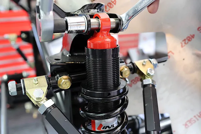
The upper ball joint must be installed, and using a vise or a large adjustable wrench is acceptable, but for this type of ball joint a local auto parts store may have the specific tool available for free rental, depending on your area. Keep in mind that the upper control arm needs to be mounted as shown in the instructions in order to make proper alignment.
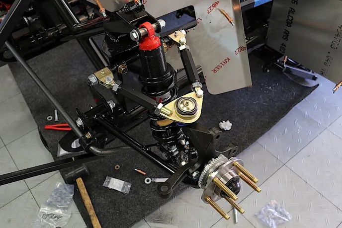
With both control arms installed, the spindles, hubs, and steering arms can be installed next. For our application, we replaced the standard FFR wheel studs with longer studs from ARP. The longer studs will allow for more thread engagement and allows for varying wheel thickness for changing wheels, or using spacers if necessary. The spindles will be marked for the proper side and the hubs are universal; they include a packed, sealed bearing.
Shocks And Springs
FFR provides a single-adjustable Koni shock absorber for each corner, or the double-adjustable shock absorber as an option. The single adjustable is used primarily for the street, and the double-adjustable shocks allow for better suspension tuning on a race track with a wide range of settings.

The settings would change for just about every track, so you can imagine that setting the compression and rebound for the street would be a never-ending series of adjustments because it all depends on the road you’re driving on. What works well on surface streets might not work as well on the freeway, so for mostly street driving the single-adjustable would be sufficient.
FFR performed testing with Koni and felt that the rates of their shock absorbers, right out of the box, were optimized for better handling on these cars. The Challenge Car is far lighter than a street car and while there are multiple settings, a driver wants to have a range in both directions to allow adjustments.
If a shock is too firm or not firm enough, it limits the settings. Other than length, shock absorbers are also valved based on the weight of the vehicle. A shock absorber for a production car would have to be firmer than for a lightweight race car, like the Challenge Car.
Of course, spring rates also come into play with the suspension and that can be a daunting task as well. Even professional race car drivers will take different weight ratings to various tracks to fine-tune their suspension. For the street, one might want a bit softer for better road comfort, but on the track a firmer spring will help with handling and to keep the car more stable at higher speeds.
The Challenge Car comes with its own spring rates from FFR, but for those who plan more street time and prefer the softer springs from the Mk4, it’s an option. Jim Schenck at Factory Five recommends about a 150-pound difference from front to rear to keep the car closer to neutral. As you might guess, the spring rates between front and rear will also affect the handling of the vehicle. Having less than that would cause more oversteer, and more would cause understeer.
The Challenge Car Series allows for spring changes, and racers will set up their car however it suits them the best. Track testing will allow a driver to dial in which spring rates are best for their particular racing style, but not everyone will use the same spring rates on the same track. Spring rates can be all over the map based on driver preference, this is why many racers will bring various springs to the track – what works on one track may not be the best setup for the next track.
Setting up the suspension can be a daunting task, and only the person behind the wheel will truly be able to tell whether the setup is working or needs to be adjusted. Schenck said, “For race guys I think listening to too many different people on setup is always an issue. Different people have different setups that all work, but when you try and combine their advice you can get very lost quickly.”
One of the worst things you can do is to make a lot of big adjustments to the shocks and the springs at the same time. Smaller adjustments always work best, because changing a spring rate and a shock setting can have an adverse affect on the handling. Schenck continued, “Also, I think people make the mistake of changing too many variable at once when tuning. The best thing to do is to make one change at a time and take really good notes during a test.”
With many people, the first thought for better handling is to firm up the suspension, and they want stiffer springs. Schenck said that while the firmer springs can be great on a fast car, it takes a while to get used to them and it’s a bit harder to drive; too often a customer will start with a stiffer spring than what they need.
FFR has being building these cars for a long time and they know what works best for each car based on where and how the car is being driven. They are there to help with the best setup from a starting point and help fine tune the suspension from there, but they won’t be able to tell you what setup is going to be the best without any information or feedback, so they do recommend that a customer starts with their recommendations and adjusts from there.
 Clamping Down With Baer Brakes
Performing the stopping duties for our Challenge Car is a set of Baer Brakes‘ 6P calipers, and 14-inch cross drilled/slotted rotors. We had the huge six-piston calipers powder coated in Fire Red to complement the whole package, and they just look incredible. This brake kit will perform great on the street, and even better on the track providing the necessary grip with the extra-large calipers and huge rotors.
We’re getting to be the wheel-designer of the brake caliper world because we have so many color and caliper options. -Rick ElamWe asked Rick Elam at Baer to explain the difference between the 6P, 6S, and 6R brake calipers. “The 6S and the 6R calipers are quite a bit more expensive as they’re a monoblock design, the 6P is a two-piece caliper.” He told us that choosing brake calipers relies on several factors, most of which is cost and how the car is being used.
“For street use, the four-piston calipers are definitely enough. But for a car that’s going to see some track time an affordable step up is the 6P,” Elam said. “For guys who are autocrossing just about every weekend, they want the best brakes they can get and will usually step up to the monoblock design.”
Elam explained that brake calipers are getting to be more like choosing wheels these days, and with the larger, wider wheels and tires enthusiasts are looking to fill the void behind the wheel with a caliper that looks great and performs just as well. “We’re getting to be the wheel-designer of the brake caliper world because we have so many color and caliper options,” he said. But that doesn’t mean function has been replaced by form, Elam says that they still try to get each customer into a brake system that works for their intended use.
The 6P brake kit is a matching front and rear caliper kit that uses smaller pistons in the rear calipers to complement the front brakes. Baer was one of the first companies to offer matching calipers for both ends of the vehicle. The calipers are a two-piece design with six cross bolts for strength, and utilize C5/C6 Corvette brake pads for ease of affordable replacement pads. The stainless steel pistons are staggered to minimize pad wear.
The rotors are a two-piece design with a 6061 T6 billet aluminum hat, anodized in black and bolted to the rotor. The hubs are also 6061 T6 billet aluminum with sealed bearings, races, and seals preinstalled. As mentioned, we opted for the longer ARP studs to accommodate any wheel or spacer that we might use, and also to allow complete thread coverage when the lug nuts are installed.
The Baer brake kit includes everything needed to install the kit, right down to the braided brake hoses. The caliper brackets bolt to the spindle, and the kit also includes shims to center the caliper on the rotor. Since this is a fixed caliper, versus a sliding caliper system, the caliper needs to be centered in order to get full clamping pressure from the brake pads.

If the caliper is not centered properly, uneven wear and even brake rotor warping can occur. To center the caliper, install it on the brackets without brake pads and tighten the mounting bolts securely. Measure the distance between the inside of the rotor to the caliper, and compare it to the outside of the rotor to the caliper. Split the difference with the appropriate spacer (supplied) and install that spacer on the bolts that will move the caliper either inward or outward to center it.
Baer supplies several spacers of varying thickness to help center the caliper, and they suggest that you don’t “eyeball it” to complete this procedure. Use measurements and the proper spacers to keep the brakes working properly, and to increase brake pad and rotor life.

Steering The Challenge Car
There are a couple of steering choices for the Mk4 and Challenge car, for our build we chose a power rack from Late Model Restoration.com to handle the steering duties. You can chose manual or power, but Schenck says that steering is more of a personal preference.
“It is more based on reaction time than steering feel,” he told us. “Because of the short wheelbase it is helpful to be able to get very quick steering inputs so most racers will opt for power.” As for the early and late model Mustang, Schenck said it’s only a difference in steering shaft adapters, but both will provide the same steering response and feel.
We installed rack adjusters by removing the inner tie rod and installing the spacer between the rack and the inner tie rod. Doing this requires cutting the inner tie rod ends to the proper length. The reason for the rack adjusters is to help align the tie rods to the axis on the upper and lower control arm pivots. Because the Mustang steering rack is not designed for this car, the rack extenders adjust the rack width to help reduce bump steer. Cutting the inner tie rod ends is to adjust the length of the tie rods once the outer tie rod end is installed.
With the Challenge car, another key factor to setting up the steering is the optional bump steer kit. While it’s not needed for the street, Schenck says there are a couple of reasons why you might need it on a race car. He said, “The first is caster adjustment; raising the caster above seven degrees starts to really affect the bump steer because as the spindle tilts back the steering arm tilts upward. Using the bump steer kit you can adjust back for the difference.”
Bump steer is what happens when your suspension compresses – it will affect the toe-in and toe-out, and that greatly affects the handling of the vehicle. Schenck continued, “The second reason is that bump steer can be used as a setup tool. On our cars, which are running a fairly edgy balance between rear weight bias and short wheelbase, it is helpful to have the wheels toe out slightly in bump to help stabilize the cars on higher speed turn in.”

The bump steer kit allows moving the pivot point up higher to reduce that bump steer. The tie rods should be at a slight upward angle, relative to the lower control arm. Because the tie rods lie in between the upper and lower control arms, they need to follow a similar arc as the control arms.
Schenck said, “The tie rod angle is affected by both arms unless it’s in the exact same plane as one of the arms.” The kit is designed to allow mounting the tie rod end above or below the steering arm to keep bump steer minimized. The steering rack is mounted into the chassis with the steering shaft installed for proper location.
To mount the rack a little bit lower in the chassis, the offset rack bushings from Late Model Restorations.com are eccentric to change how the gear mounts. By moving the rack lower in the chassis, that aids with the reduction of bump steer. Every little bit helps, and each of these modifications will make a small difference individually, but a big difference on the whole. The installation of these offset rack bushings will vary, depending on the vehicle and application. For our Challenge Car project, Schenck said getting the rack as low as possible in the chassis is the goal, so we installed the eccentric bushings to accomplish that.
 With most street cars, the alignment for the steering usually has a slight toe-in. That will provide better tire wear and road feel, but for a performance car that sees a lot of track time most racers will opt for a little bit of toe-out for better cornering. This could slightly wear your tires quicker on the street for a daily driver, but fast cornering will trump street alignment every time.
FFR recommends about 3 degrees of negative camber, and seven degrees of positive caster with 1/8-inch toe out for better handling. If the car is driven on the street quite often, an owner might want to go far less camber and a little toe in to decrease tire wear.
For the Challenge car, the suspension and wheel/tire combo would typically lower the car a bit more than the Mk4 Roadster, therefore, the need for a bump steer kit and rack extenders are included with the Challenger car. These kits should be considered for the Mk4 Roadster, especially if the car sees a bit of track time.
With that, we have completed the front suspension installation and are moving on to the rear suspension with a new Moser rearend built with Baer’s floating hubs for superior on-track performance. Keep up with us on the project build thread, or the Project FFR Cobra Jet Challenge Car page.
You might also like
This Mid-Engine Small-Block Corvair Is Unlike Anything Chevrolet Ever Built
See how a 1965 Corvair became a 500-hp mid-engine Chevy 350 street machine with custom steel bodywork built over 45 years ago.