Establishing the perfect stance for your project is one of the most important details. In the case of Tiger’s Eye, Rod Authority’s kustom 1950 Chevrolet Fleetline, we needed to achieve two things: an aggressively lowered ride height and turnkey height & spring rate adjustability. We reached out to our friends at Total Cost Involved Engineering in Ontario, California to help us achieve the stance that we were looking for. Follow alongside our shop manager, Sean Goude, as he walks us through the installation and also offers builder’s tips for the DIY crowd.
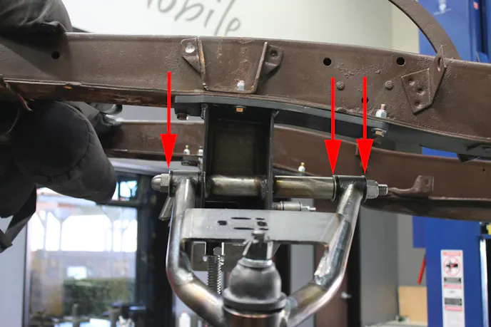
Sean’s Tip #1: When mocking up the crossmember measure diagonally from the front bolt to the rear bolt, for both sides, in order to confirm that the crossmember is squared.Why Does It Have To Sit That Low? It Looks Like All The Springs Snapped
Simply put, a lowered ride height is indicative of a kustomizer’s attitude. It is the rooster touting its red crest while galavanting past a coupe of hens. It is a Siamese Fighting Fish flaring its gills when facing down an opponent. It is a design element that spans back to post-World War II and the forefathers of kustom cars–only these days heating and cutting coils has been replaced with modern aftermarket technology.
If “Slamming” Your Ride Is So Important Why Is Adjustability A Concern?
Turnkey adjustability is the second detail that lead us to choose airbag suspension over an OE coil and leaf spring setup. When it comes to aggressively lowering Tiger’s Eye, or any kustom for that matter, static suspension poses several problems:
First, when you lower and commit your vehicle to a fixed ride height you sacrifice undercarriage clearance. When speed bumps and high angle driveways become a serious concern there is no amount of kool that will get you through those situations. In that moment you will find yourself wishing that you had the ability to add a few inches of clearance in order to gracefully glide over said obstacles. Air suspension makes this a possibility by affording a driver the ability to increase ride height and seamlessly drop back down to a desired stance after besting the terrain, all with the flick of a switch.
Second, when you choose traditional suspension over the turnkey adjustability of air ride your suspension’s spring rate is not optimized for the variable gross weight of your vehicle. According to Performance Trends Inc., a company producing quality computer tools for racers and engine builders since 1986, spring rate is defined as the amount of weight it takes to compress a spring a certain distance.
In our case passengers, luggage, and supplies for prolonged travel pose the greatest factor for variable gross weight. Because Tiger’s Eye is being built as a show car and long distance cruiser the vehicle will be seeing anywhere from one to six passengers at any given time. If cargo load can change dramatically shouldn’t spring rate be able to do the same?
With the ability to adjust PSI in each individual air spring we will have the ability to create the perfect ride quality even if that means we have a cabin with a 180-pound driver, a 300-pound friend in the front passenger seat, three in the back with a combined weight of 700-pounds, and a trunk full of baggage & supplies.

Sean’s Tip #3: If some of the factory holes aren’t lining up with your kit don’t be afraid, anxious, or stressed out–run a drill bit through the factory holes and shave off some material to make it work.Why TCI Engineering? Getting Familiar With Their Product Applications
Now that we’ve offered our two cents regarding the qualities of air suspension let’s take a quick look at TCI Engineering’s catalog of IFS, rear suspension, and chassis offerings. Their 40-years in the industry, American-made products, and six year/60,000 mile warranty (link this once that news article goes live) are just some of the reasons that made it easy when choosing who to include on such an integral portion of our project build.
TCI Engineering specializes in the manufacturing of aftermarket chassis for 1932 Fords and 1947-1954 Chevy & GMC trucks.
Another portion of their business is dedicated to offering bolt-on and weld-on IFS and rear suspension packages for the following vehicle groups:
- Ford Street Rods
- 1928-1948 Ford Car
- Ford Classic Trucks
- 1928-1941 & 1948-1964 Ford Truck
- Ford Muscle Cars
- 1964.5-1970 Mustang, 1967-1969 Cougar, 1966-1967 Fairlane, 1960-1965 Falcon, 1962-1965 Comet, 1962-1965 Ranchero
- Chevrolet Street Rods
- 1928-1954 Chevy Car
- Chevrolet Classic Trucks
- 1937-1959 & 1963-1987 Chevy Truck
- Chevrolet Muscle Cars
- 1967-1981 Camaro/Firebird, 1962-1974 Nova
Rod Authority’s IFS Kit Contents & Options At A Glance
- Reinforced 3/16-inch crossmember
- 1-inch performance anti-roll bar
- Anti-roll bar heim joints
- Upper spring towers
- Upper air spring mounting cups
- 1-inch x .156w US DOM upper A-arm: plain steel
- 1 1/8-inch x .156w US DOM lower A-arm: plain steel
- Bump stops and mounting brackets
- Standard GM calipers
- 11-inch rotors, 4 3/4-inch bolt pattern: plain
- Painted shocks and mounting brackets
- ALL mounting hardware
- Installation manual
- Kit Options: 2-inch drop spindles | Power rack and pinion steering | Double convoluted air springs
TCI Engineering Helps Tiger’s Eye Get Low And Improves Performance
The stout list of application offerings above proved to us that TCI Engineering has spent a great deal of resources towards R&D of products catering to years and makes that are right up our alley. We were more than confident when looking to them as a source for our independent front suspension setup. For our install we chose TCI Engineering’s bolt-on IFS for 1949-1954 Chevy Classic Cars (PN: 224-2354-00). Based on the tried and true Mustang II spindle design, TCI Engineering’s IFS package boasts some added benefits:
- Crossmember: 3/16-inch thick ASTM A-1011 steel plate welded in-house for quality control, aka, peace of mind
- Heavy duty ball joints and control arms for bolstered strength
- All mounting hardware included
- 1-inch diameter anti-roll bar provides greater roll control
- Increased camber gain keeps tires flat on the ground for additional grip
- Anti-dive control keeps tires planted during aggressive braking
- Polyurethane bushings provide road noise dampening
Jason Wilcox at TCI Engineering explained, “We’ve spent a lot of time engineering our IFS packages to create a setup that addresses three important details: lowering center of gravity, decreasing body roll, and increasing handling.”
Lowering Oneself (Or Car) To Achieve Success
First we mocked up the crossmember into the correct mounting position. TCI Engineering’s installation manual (included with the kit) provides a clear diagram for reference. Using factory holes on the frame we located a reference point and plotted drill points for the rest of the crossmember’s bolt locations.


The rest of the crossmember’s mounting holes use 3/8-inch hardware included with the kit. These are all torqued to 45 foot-pounds as well.
Next we mounted the lower control arms. The acorn side of the 5/8-inch shaft should be facing towards the front of the vehicle.
After the lower control arms are mounted we used a cutoff wheel to remove the front portion of the factory frame bracket, pictured below. This material needs to be removed from both driver and passenger side in order for the spring towers to be installed.
Next we moved to the installation of our spring towers. The tall part of the upper control arm mount faces the front of the vehicle. This is TCI Engineering’s built-in anti-dive feature that we mentioned in the “TCI Engineering Helps Tiger’s Eye Get Low And Improves Performance” section of this article. The mounting of the spring towers requires precise measuring. We referenced the diagram below in order to properly locate and weld our spring towers.


Next we installed the bump stop brackets included with TCI Engineering’s IFS kit. Again, we referenced the bolt hole location diagram and saw that the bump stop brackets were mounted using position #6 and #7 with the bump stop itself facing outward, tapered side facing down.
We then mocked up the upper air spring mounting cups and air springs. By compressing the air springs we confirmed proper spring cup/lower control arm alignment, bump stop location, and air spring travel during inflation & deflation. With the more technical portions of this install behind us we secured the bump stops and air springs into place and charged full steam ahead towards completion.


With the upper control arms secure we installed the spindle assemblies next. We mounted the spindle onto the lower ball joint with the steering arm facing towards the front of the vehicle. Once secure we torqued the lower control arm to 90 foot-pounds and the upper control arm to 70 foot-pounds. We used TCI Engineering’s ball joint washers, castle nuts and cotter pins included in the kit to complete this step.
With the spindle assemblies secure we welded our shock mounts into place. At this point we are home free; all that was left was to mount the power steering assembly, anti-roll bar, and heim joints. The most important portion of this last stretch was to make sure that we centered our steering assembly before we connected the tie rod ends to the steering arms. 
We’ll leave you with an easy step by step for measuring and centering your steering assembly for proper mounting:
1. On a stable surface such as a work bench turn the pinion out so that it is fully locked one way.
2. Choose a reference point and measure out towards the extended end of the inner tie rod. From our reference point we measure the rack at 16 7/8-inches.
3. Turn the pinion in the opposite direction until it locks out on the opposite side. Using the same side that we measured from in step 2, we measured from the same reference point to the end of the same inner tie rod. From our reference point the compressed rack is 10 7/8-inches.
4. Subtract the measurement of step 3 from step 2; the difference is 6-inches in our case.
5. Divide the difference from step 4 by 2; the quotient was 3-inches in our case.
6. Add the quotient (3-inches) to the measurement from step 3; the sum was 13 7/8-inches in our case. From there we measured from the reference point and turned the pinion until the end of the inner tie rod measured 13 7/8-inches. The rack and pinion steering assembly is now centered.
 With TCI Engineering’s IFS kit installed we mounted our wheels & tires and got our frame back on the ground in less than a full work day. Even though we still have to plumb the air suspension, the day’s work revealed a glimpse of the aggressively altered stance of our frame at rest. For a kustom, stance is everything. We wanted to make sure that we took it to the next level by melding extremely altered ride height with the practicality and convenience of turnkey adjustability.
Stay tuned for the next feature in the Tiger’s Eye project series. We cover the assembly and mounting of the powerplant & transmission propelling us ever-closer to getting our body back on the frame.
After reading this install coverage what are your impressions of air suspension? Is it cheating or is it a God-send? We know what we like, but we want to know what you have to say–leave your comments below!
You might also like
Project F-Zilla Is Getting A 764-Horsepower Heart Transplant
The Bosszilla engine build combines heavy-duty forged internals and custom geometry to create a 764-horsepower naturally aspirated monster.